Eletrification
Eletrification
In the modern industrial landscape, the transition toward eletrification represents more than just a shift in power sources; it is a fundamental evolution in how process data is captured, transmitted, and utilized. For plant engineers and system integrators, eletrification in the context of level measurement involves moving away from manual gauging and pneumatic controls toward sophisticated, electrically powered sensors that integrate seamlessly with digital automation architectures.
As a professional manufacturer, Welk provides the hardware necessary to support this transition, offering a suite of radar, ultrasonic, and hydrostatic instruments designed for the rigors of electrified industrial environments. This guide examines the principles of these technologies, their role in an electrified facility, and the critical factors to consider when selecting and installing these systems.
Principles of Industrial Level Measurement
Before implementing an electrified level control strategy, it is essential to understand the physical principles that govern different measurement technologies. Each method interacts with the process media and the electrical system in unique ways.
Radar Level Measurement (Time of Flight)
Radar level meters operate on the Time of Flight (ToF) principle. The instrument emits high-frequency electromagnetic pulses (typically in the GHz range) toward the material surface. These pulses are reflected back to the sensor. Since the speed of light is constant, the time delay between transmission and reception allows the internal processor to calculate the distance with extreme precision. In an electrified plant, radar is preferred for its non-contact nature and immunity to vacuum, high pressure, and temperature fluctuations.
Ultrasonic Level Sensors (Acoustic Reflection)
Similar to radar, ultrasonic sensors use the ToF principle but rely on sound waves rather than electromagnetic waves. A transducer emits an ultrasonic pulse that travels through the air gap, hits the liquid or solid surface, and returns. The device measures the time interval and compensates for the speed of sound based on the ambient temperature. These are cost-effective solutions for water treatment and open-channel flow applications.
Hydrostatic Level Transmitters (Pressure-Based)
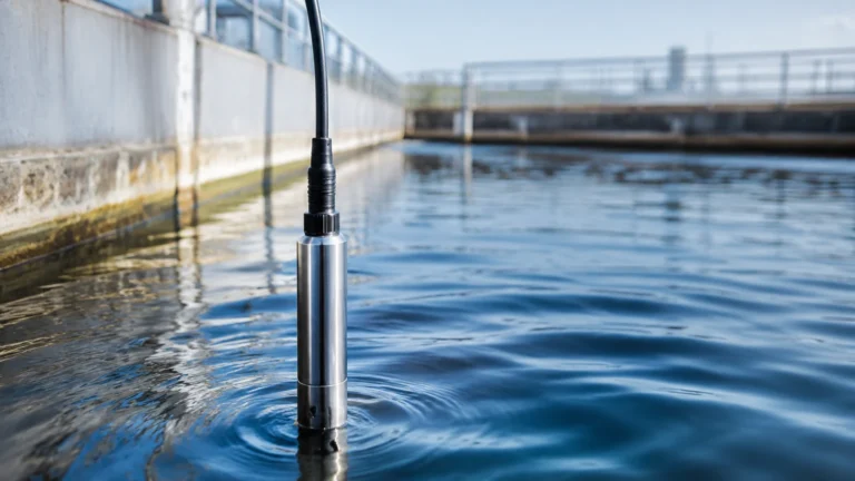
Hydrostatic measurement is based on the principle that the pressure at a specific depth in a static liquid is proportional to the height of the liquid column above it. The formula $P = \rho \cdot g \cdot h$ (where $P$ is pressure, $\rho$ is density, $g$ is gravity, and $h$ is height) allows the sensor to determine the level by measuring the pressure exerted on a diaphragm. These sensors are typically submerged or mounted to the bottom of a vessel and convert the physical pressure into an electrical signal, such as 4-20mA.
Magnetic Level Gauges and Switches
Magnetic gauges utilize a float containing a high-intensity magnet that moves with the liquid level. This float interacts with an external indicator or a series of reed switches. While the primary indication can be mechanical, eletrification allows for the addition of reed transmitters that convert the float position into a continuous electrical output for remote monitoring.
The Role of Eletrification in Process Automation
The process of eletrification in industrial facilities involves the integration of field instruments into a centralized control system, such as a PLC (Programmable Logic Controller) or SCADA (Supervisory Control and Data Acquisition) system. This integration provides several advantages over traditional mechanical systems:
1. Real-Time Data Acquisition: Electrified sensors provide instantaneous feedback, allowing for tighter control loops and immediate response to process upsets.
2. Remote Monitoring: Data can be transmitted over long distances via current loops or digital protocols, removing the need for personnel to manually check tank levels in hazardous or remote areas.
3. Enhanced Accuracy: Digital signal processing within modern level meters can filter out noise and false echoes, providing a level of precision that mechanical gauges cannot match.
4. Predictive Maintenance: Many electrified instruments include self-diagnostic features that alert operators to sensor fouling or hardware failure before a total system shutdown occurs.
To explore the full range of industrial sensors and their integration capabilities, visit the Main Page.
Technology Selection Criteria
Choosing the right instrument for an electrified system requires an evaluation of both the process media and the electrical infrastructure. Engineers should consider the following criteria:
| Technology | Best For | Accuracy | Limitations |
| :— | :— | :— | :— |
| Radar | Corrosive chemicals, high temp/pressure | ±2mm to ±5mm | Higher initial cost |
| Ultrasonic | Water, wastewater, open tanks | ±0.25% of range | Affected by heavy foam or vacuum |
| Hydrostatic | Deep wells, vented tanks, oils | ±0.1% to ±0.5% | Dependent on constant fluid density |
| Magnetic | High-pressure boilers, toxic liquids | ±5mm to ±10mm | Moving parts may require cleaning |
Media Characteristics
The dielectric constant of the material is critical for radar, while the density is the primary factor for hydrostatic sensors. If the media produces heavy foam, ultrasonic waves may be absorbed, making radar or hydrostatic options more reliable.
Power Supply and Output
Most industrial level meters operate on 24V DC loop power. However, some high-accuracy radar units may require a 4-wire connection with a separate power supply. Common output signals include 4-20mA (with HART protocol), Modbus RS485, or Profibus, which must be compatible with the facility's existing eletrification framework.
Installation and Engineering Considerations
Successful eletrification of level measurement depends heavily on proper installation. Electrical interference and physical positioning are the two most common causes of signal failure.
Wiring and Shielding
In environments with large motors or variable frequency drives (VFDs), electromagnetic interference (EMI) can distort the 4-20mA signal. It is mandatory to use shielded twisted-pair cabling and ensure that the shield is grounded at only one end (typically the control room side) to prevent ground loops.
Grounding and Surge Protection
Electrified instruments are susceptible to voltage surges caused by lightning or switching transients. Proper earthing of the sensor housing and the use of surge protection modules are essential for protecting the internal electronics, especially in outdoor installations like water reservoirs or oil tank farms.
Mounting Position
For non-contact sensors (Radar and Ultrasonic), the beam must have a clear path to the liquid surface. Obstructions such as agitators, ladders, or inlet pipes can create false echoes. Most modern Welk instruments allow for "false echo suppression," where the software is programmed to ignore static reflections from internal tank structures.

Risks and Limitations of Electrified Systems
While eletrification provides significant benefits, it introduces specific risks that must be managed:
* Power Dependency: Unlike a purely mechanical float gauge, an electrified sensor requires a stable power source. Critical applications should include Uninterruptible Power Supplies (UPS) to maintain visibility during outages.
* Signal Noise: In a densely packed electrical cabinet, crosstalk between signal wires can lead to erratic readings. Proper segregation of power and signal cables is required.
* Environmental Hazards: In oil and gas or chemical industries, the electrical components must be housed in explosion-proof (Ex d) or intrinsically safe (Ex ia) enclosures to prevent the instrument from becoming an ignition source in flammable atmospheres.
Frequently Asked Questions (FAQ)
Q: Can I replace a mechanical float gauge with an electrified radar meter without modifying the tank?
A: In many cases, yes. Radar meters can often be mounted on existing nozzles. However, you must ensure the nozzle diameter and height do not interfere with the radar beam angle.
Q: How does temperature affect electrified level sensors?
A: Ultrasonic sensors are highly sensitive to temperature because it changes the speed of sound; they require integrated temperature compensation. Radar is largely unaffected by temperature changes in the vapor space.
Q: What is the maximum distance for a 4-20mA signal in an electrified plant?
A: Typically, a 4-20mA signal can travel up to 1,000 meters (approx. 3,280 feet) depending on the wire gauge and the total loop resistance. For longer distances, digital communication like Modbus or wireless transmission is recommended.
Q: Is eletrification suitable for highly viscous liquids?
A: Yes, but the technology choice is key. Non-contact radar is excellent for viscous liquids because it does not touch the media, preventing buildup on the sensor.
Conclusion
The move toward industrial eletrification is an essential step for facilities aiming to improve efficiency and data accuracy. By transitioning to electrified level measurement solutions—such as those provided by Welk—operators gain the ability to monitor processes with unprecedented precision. Whether implementing radar for complex chemical reactors or hydrostatic transmitters for water management, understanding the underlying measurement principles and electrical requirements ensures a robust and reliable installation. Before proceeding with a project, engineers should confirm the chemical compatibility of the wetted parts, the electrical classification of the installation area, and the integration requirements of the control system.