Endress Hauser Level Sensor
Endress Hauser Level Sensor
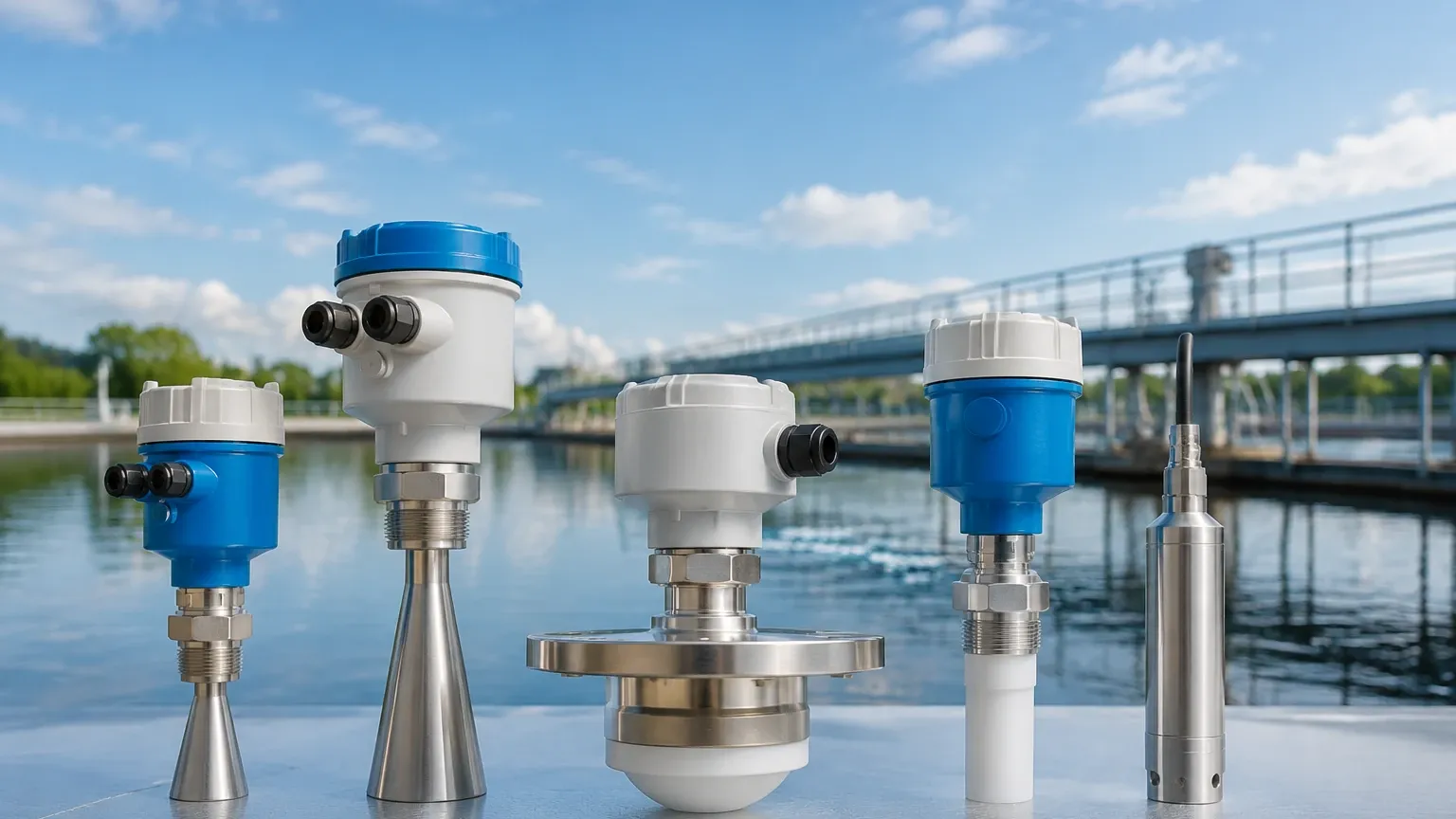
In the landscape of industrial automation, precise level measurement is a cornerstone of process safety, inventory management, and operational efficiency. Selecting an instrumentation solution, such as an Endress Hauser level sensor, requires a deep understanding of the physics behind the measurement and the specific environmental constraints of the application. Whether managing aggressive chemicals in a processing plant or monitoring water levels in municipal infrastructure, the choice of technology dictates the long-term reliability of the data. This guide explores the fundamental principles, selection criteria, and engineering considerations essential for integrating high-performance level sensors into modern industrial systems.
Understanding Level Measurement Principles
Before selecting a specific instrument, engineers must evaluate the physical principle that best suits the medium and the vessel. Level measurement technologies are generally categorized into continuous measurement and point level detection. Within these categories, several distinct physical phenomena are utilized.
Radar Level Measurement (ToF)
Radar sensors operate on the Time-of-Flight (ToF) principle. The device emits high-frequency electromagnetic pulses (typically in the 26 GHz or 80 GHz range) toward the product surface. These pulses are reflected by the medium's surface and received by the sensor's antenna. The distance is calculated based on the time it takes for the pulse to travel to the surface and back.
* Free-Space Radar: Non-contact measurement ideal for corrosive or hygienic applications. High-frequency 80 GHz radar allows for smaller beam angles, reducing interference from tank internals.
* Guided Wave Radar (GWR): Uses a physical probe (cable or rod) to guide the microwave pulse. This is particularly effective in applications with low dielectric constants or where heavy foam and turbulence are present.
Ultrasonic Level Measurement
Ultrasonic sensors emit mechanical sound waves. The elapsed time between emitting the ultrasonic pulse and receiving the echo is proportional to the distance. This technology is cost-effective and widely used in water and wastewater treatment. However, it is sensitive to changes in the gas phase composition, temperature fluctuations, and vacuum conditions, as sound requires a medium to travel through.
Hydrostatic Level Measurement
Hydrostatic sensors measure the pressure exerted by a liquid column. According to the hydrostatic paradox, the pressure at the bottom of a tank is directly proportional to the height of the liquid and its specific gravity ($P = \rho \cdot g \cdot h$). These sensors are typically submerged or mounted at the bottom of the vessel. They are highly reliable for vented tanks but require compensation for vapor pressure in sealed pressurized vessels.
Capacitance Level Measurement
This principle treats the sensor probe and the vessel wall as two electrodes of a capacitor. As the level rises, the dielectric constant between the electrodes changes (since most liquids have a higher dielectric constant than air), leading to a change in capacitance that is converted into a level signal. This is robust for both liquids and bulk solids but requires recalibration if the medium's dielectric properties change significantly.
Key Evaluation Criteria for Sensor Selection
When evaluating an Endress Hauser level sensor or a comparable high-precision instrument from manufacturers like Welk, several technical parameters must be cross-referenced with the process environment.
Media Characteristics
The physical and chemical properties of the substance being measured are the primary drivers of technology selection.
* Dielectric Constant ($ε_r$): Crucial for radar and capacitance sensors. Low $ε_r$ fluids (like hydrocarbons) reflect less energy, often necessitating guided wave radar.
* Viscosity and Coating: Highly viscous media can build up on probes. In such cases, non-contact radar or vibrating fork switches are preferred over contact-based displacement or capacitance probes.
* Corrosivity: For aggressive acids or bases, sensors must feature wetted parts made of PTFE, PVDF, or high-grade alloys like Hastelloy.
Process Conditions
* Temperature: Industrial processes can range from cryogenic levels to over 400°C. Sensors must be rated for these extremes, often requiring cooling extensions or specialized ceramic seals.
* Pressure: High-pressure reactors (exceeding 100 bar or 10 MPa) require robust process connections and sensor housings that can withstand mechanical stress without compromising the seal.
* Turbulence and Foam: Surface agitation can scatter radar and ultrasonic signals. While radar can often penetrate thin foam, thick or dense foam may require GWR or hydrostatic solutions.
Practical Selection Table for Industrial Applications
The following table provides a generalized comparison of common level measurement technologies used in B2B industrial environments.
| Technology | Typical Accuracy | Max Range | Contact | Suitability for Foam | Best For |
| :— | :— | :— | :— | :— | :— |
| 80 GHz Radar | ±1 mm | 125 m | No | Moderate | Chemical tanks, tall silos |
| Guided Wave Radar | ±2 mm | 45 m | Yes | Excellent | Low dielectric liquids, bypass pipes |
| Ultrasonic | ±2 mm | 15 m | No | Poor | Open channels, water sumps |
| Hydrostatic | ±0.1% FS | 700 m (H2O) | Yes | Excellent | Deep wells, pressurized tanks |
| Capacitance | ±1% FS | 10 m | Yes | Good | Interface measurement, solids |
For engineers seeking a comprehensive overview of available hardware and technical specifications, it is advisable to Review product options and application support on the Main Page of specialized manufacturers to ensure the selected hardware aligns with specific regional and industry standards.
Installation and Engineering Best Practices
The performance of even the most advanced Endress Hauser level sensor is heavily dependent on correct installation. Failure to account for vessel geometry can lead to false echoes and signal loss.
1. Nozzle Dimensions: For non-contact radar, the nozzle height and diameter must be optimized. If a nozzle is too long or narrow, the radar beam may reflect off the nozzle wall before reaching the medium. Generally, the sensor antenna should protrude slightly beyond the nozzle neck.
2. The 1/6th Diameter Rule: To avoid interference from the vessel wall and the effects of the parabolic shape of the liquid surface during filling/emptying, sensors should ideally be mounted at a distance of 1/6th of the tank diameter from the wall.
3. Dead Zones (Blocking Distance): Every ultrasonic and radar sensor has a "dead zone" near the antenna where measurement is impossible. This must be accounted for when calculating the maximum fill level to prevent the medium from entering the blocking distance.
4. Internal Obstructions: Agitators, heating coils, and ladders create "parasitic" echoes. Modern sensors use "Mapping" or "False Echo Suppression" software to record these static reflections and ignore them during active measurement. However, it is always best to install the sensor in a clear path to the liquid surface.
Overcoming Common Measurement Challenges and Risks
In demanding industrial sectors like oil and gas or chemical processing, certain risks can compromise measurement integrity.
Condensation and Buildup
In many aqueous applications, condensation forms on the sensor face. While 80 GHz radar is less sensitive to this than ultrasonic technology, heavy buildup can still attenuate the signal. Utilizing sensors with drip-off antenna designs or integrated air purging systems can mitigate this risk. Manufacturers like Welk often provide customized OEM solutions that include specialized flange designs to prevent buildup in high-humidity environments.
Varying Vapor Phases
In high-pressure boilers, the gas phase above the liquid is not air but high-pressure steam. This changes the speed of sound (affecting ultrasonic) and the dielectric constant of the gas (affecting radar). In these specific cases, Guided Wave Radar with "Gas Phase Compensation" is required. This technology uses a reference reflection at a known distance to calculate the actual propagation speed of the pulse in the current vapor environment.
Safety Integrity Levels (SIL)
For applications involving hazardous materials, the level sensor is often part of a Safety Instrumented System (SIS). It is critical to confirm that the sensor is SIL2 or SIL3 certified according to IEC 61508. This ensures that the device has a high probability of performing its safety function (e.g., preventing an overfill) when called upon.
Frequently Asked Questions (FAQs)
Q: Can one sensor type be used for both liquids and solids?
A: While some radar sensors are versatile, bulk solids present different challenges, such as steep angles of repose and dust. Radar sensors for solids often require specialized lenses and higher power to penetrate dust clouds and reflect off uneven surfaces.
Q: How often does a level sensor require calibration?
A: This depends on the technology. Hydrostatic and capacitance sensors may drift over time and usually require annual checks. Non-contact radar is inherently more stable but should be verified periodically as part of a standard maintenance cycle, especially in regulated industries like food and pharma.
Q: What is the advantage of 80 GHz over 26 GHz radar?
A: The primary advantage is the beam angle. An 80 GHz sensor has a much narrower beam, allowing it to "see" past internal obstructions and be used in narrow tanks or through smaller nozzles without interference.
Q: How do I measure the interface between two liquids?
A: Guided Wave Radar is the industry standard for interface measurement (e.g., oil and water). The pulse reflects off the top layer (low dielectric) and continues through to reflect off the second layer (high dielectric), providing both the total level and the interface level.
Conclusion
Selecting an industrial level measurement solution requires a balance between technical capability and cost-effectiveness. While an Endress Hauser level sensor offers high-end performance for complex process environments, understanding the underlying physics allows engineers to choose the most appropriate tool for their specific needs. By focusing on media properties, process conditions, and rigorous installation standards, facilities can achieve reliable, long-term level monitoring. For further technical specifications and a range of industrial-grade measurement instruments, visiting the Main Page of an established manufacturer provides the necessary context for final project procurement.