External Flow Meter
External Flow Meter
In the landscape of industrial process control, the ability to measure fluid movement without interrupting operations is a significant technical advantage. An external flow meter, most commonly represented by clamp-on ultrasonic technology, provides a non-invasive solution for monitoring flow rates in pipes. Unlike traditional inline meters that require pipe cutting, flanges, and potential process downtime, external flow meters are mounted to the outside of the conduit. This engineering guide explores the principles, selection criteria, and installation requirements for external flow measurement systems used in modern B2B industrial environments.
Industrial facilities, ranging from water treatment plants to chemical processing units, often face the challenge of retrofitting measurement points into existing infrastructure. For many of these applications, the integration of an external flow meter is the most cost-effective and low-risk strategy. To understand how these devices complement a broader instrumentation strategy, including level and pressure monitoring, engineers often consult the Main Page for a comprehensive overview of industrial sensing solutions.
Measurement Principles of External Flow Meters
External flow meters primarily utilize ultrasonic energy to determine the velocity of a fluid within a pipe. Because the sensors do not come into contact with the medium, the measurement is independent of fluid conductivity, pressure, and chemical corrosivity. There are two primary physical principles employed in these devices: Transit-Time and Doppler Effect.
Transit-Time Technology
Transit-time ultrasonic meters are the most common type of external flow meter for clean liquids. The system utilizes two transducers that function as both transmitters and receivers. These transducers are clamped to the outside of the pipe at a specific distance from each other.
The principle relies on the fact that sound waves travel faster when moving with the flow (downstream) than when moving against it (upstream). The meter sends a pulse from Transducer A to Transducer B, and then from B to A. The difference in the time it takes for these pulses to travel is directly proportional to the velocity of the liquid. Once the velocity is known, and the internal cross-sectional area of the pipe is programmed into the transmitter, the volumetric flow rate is calculated.
Doppler Effect Technology
While transit-time meters require relatively clean fluids, Doppler external flow meters are designed for liquids containing suspended solids or entrained air bubbles (aeration). The transducers transmit an ultrasonic signal of a known frequency into the liquid. This signal reflects off the particles or bubbles moving with the fluid. Due to the Doppler effect, the frequency of the reflected signal is shifted. The meter measures this frequency shift to determine the flow velocity.
Key Evaluation Criteria for Selection
Selecting the correct external flow meter requires a detailed understanding of the application environment. Because the signal must pass through the pipe wall, the physical characteristics of the pipe are as important as the fluid properties.
Pipe Material and Condition
External flow meters work best on homogeneous pipe materials such as carbon steel, stainless steel, copper, and most plastics (PVC, PE, PVDF). Materials that are non-homogeneous or porous, such as concrete-lined pipes or heavily corroded cast iron, can attenuate or scatter the ultrasonic signal, making measurement difficult. Engineers must confirm the pipe's outer diameter (OD) and wall thickness using ultrasonic thickness gauges before finalizing a meter selection.
Fluid Characteristics
For transit-time meters, the fluid should ideally contain less than 2% total suspended solids (TSS) or bubbles by volume. If the fluid is a heavy slurry or highly aerated, a Doppler-based external flow meter is required. Additionally, the fluid's sonic velocity (the speed at which sound travels through the liquid) must be known or selectable from the meter's internal library.
Temperature Ranges
Standard external transducers are typically rated for temperatures up to 80°C (176°F). For high-temperature applications, such as boiler feed water or thermal oil loops, specialized high-temperature transducers and mounting tracks are required to prevent damage to the piezoelectric elements.
Selection Table: Transit-Time vs. Doppler
| Feature | Transit-Time External Meter | Doppler External Meter |
| :— | :— | :— |
| Fluid Type | Clean liquids, water, oils, chemicals | Slurries, wastewater, aerated liquids |
| Suspended Solids | < 2% by volume | > 100 ppm of particles > 75 microns |
| Accuracy | ±0.5% to ±2.0% of velocity | ±2.0% to ±5.0% of velocity |
| Pipe Size Range | 15 mm to 6,000 mm (0.5" to 240") | 25 mm to 6,000 mm (1.0" to 240") |
| Typical Applications | Potable water, cooling water, HVAC | Raw sewage, mining slurries, paper pulp |
Installation Considerations and Best Practices
The performance of an external flow meter is heavily dependent on the quality of the installation. Unlike inline meters, where the manufacturer controls the flow profile within the meter body, external meters rely on the user to identify a suitable location on the existing piping.
Straight Pipe Requirements
To ensure a stable and accurate reading, the flow profile must be fully developed and free of turbulence. This is achieved by installing the sensors on a straight section of pipe. The standard industry recommendation is:
* Upstream: At least 10 pipe diameters (10D) of straight pipe after any bends, valves, or pumps.
* Downstream: At least 5 pipe diameters (5D) of straight pipe before the next fitting.
If the installation follows a pump or a partially open valve, the upstream requirement may increase to 20D or 30D to allow turbulence to subside.
Mounting Methods
There are three primary ways to mount the transducers, depending on the pipe size and signal strength:
1. V-Method: The signal bounces off the opposite pipe wall once. This is the standard method for pipes ranging from 25 mm to 400 mm (1" to 16").
2. Z-Method: Transducers are mounted on opposite sides of the pipe. The signal passes through the fluid only once. This is used for large pipes (over 400 mm) or pipes with high signal attenuation.
3. W-Method: The signal bounces three times. This is used for very small pipes (typically under 50 mm) to increase the time-of-flight and improve resolution.
Coupling Agents
Since air is a poor conductor of ultrasonic waves, a coupling agent (acoustic gel or grease) must be applied between the transducer face and the pipe surface. This eliminates air gaps and ensures efficient signal transmission. For permanent installations, solid coupling pads or high-temperature silicone may be used to prevent the gel from drying out over time.
Limitations and Risks
While the external flow meter is a versatile tool, it is not a "one-size-fits-all" solution. Engineers should be aware of the following limitations:
* Pipe Linings: If a pipe has a liner (e.g., rubber or cement) that is not perfectly bonded to the outer wall, an air gap may exist. This gap will block the ultrasonic signal entirely.
* Signal Attenuation: Extremely thick-walled pipes or pipes with heavy internal scaling can absorb the ultrasonic energy, leading to a "Low Signal" error.
* Flow Profile Sensitivity: Because these meters measure velocity at a specific path, they are more sensitive to non-uniform flow profiles than some inline technologies.
* Ambient Noise: In rare cases, high-frequency mechanical vibration from nearby heavy machinery can interfere with the ultrasonic signal.
Integration into Industrial Automation
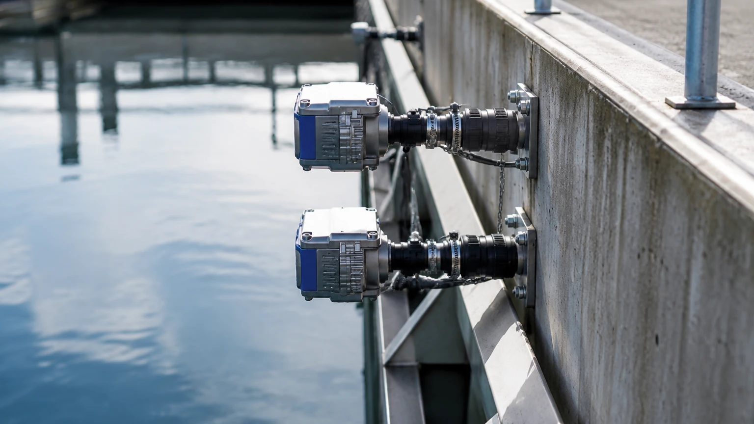
External flow meters are rarely standalone devices. In a B2B context, they are integrated into SCADA or PLC systems via 4-20mA analog outputs, Modbus RTU, or HART protocols. This connectivity allows for real-time monitoring of mass flow, totalization, and energy (BTU) measurement in heating and cooling systems.
For facilities looking to standardize their instrumentation, it is helpful to source flow meters from providers who also understand level measurement. The synergy between flow and level data is critical in applications like tank inventory management and open channel flow calculation. You can review various measurement technologies and support options at the Main Page.
Frequently Asked Questions (FAQ)
Q: Can an external flow meter measure gas flow?
A: Most standard external meters are designed for liquids. While specialized high-power ultrasonic meters exist for high-pressure gas pipes, they are significantly more expensive and technically demanding than liquid versions.
Q: Does the pipe need to be full?
A: Yes. For accurate measurement, the pipe must be completely full of liquid. If the pipe is partially full, the meter will either provide an erroneous reading or fail to receive a signal because the sound waves cannot travel through the air space at the top of the pipe.
Q: How often does the meter need recalibration?
A: Since there are no moving parts and no contact with the fluid, the electronic calibration of the meter remains stable for many years. However, the coupling gel should be inspected periodically (every 1-2 years) to ensure it hasn't dried out, which would weaken the signal.
Q: Can it measure flow through plastic pipes?
A: Yes, ultrasonic waves travel very well through most plastics like PVC, HDPE, and PP. It is often easier to get a signal through plastic than through thick-walled metal pipes.
Conclusion
The external flow meter represents a pinnacle of convenience and efficiency in industrial instrumentation. By eliminating the need for pipe modifications and process shutdowns, it provides a path to better data without the traditional costs of installation. When applied with a proper understanding of pipe acoustics and flow dynamics, these devices offer the reliability and accuracy required for critical process control. For engineers seeking to optimize their entire measurement suite, from flow to level, visiting the Main Page provides the necessary technical resources to make informed procurement decisions.