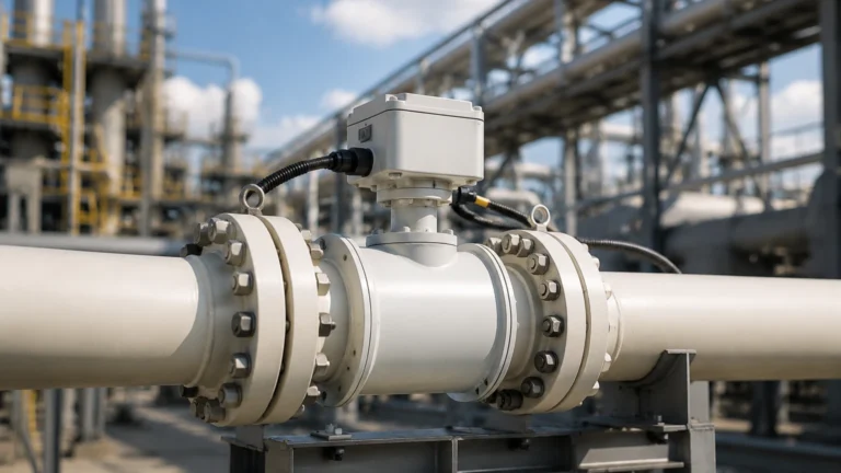
Fast Response Pressure Transducer
Fast Response Pressure Transducer
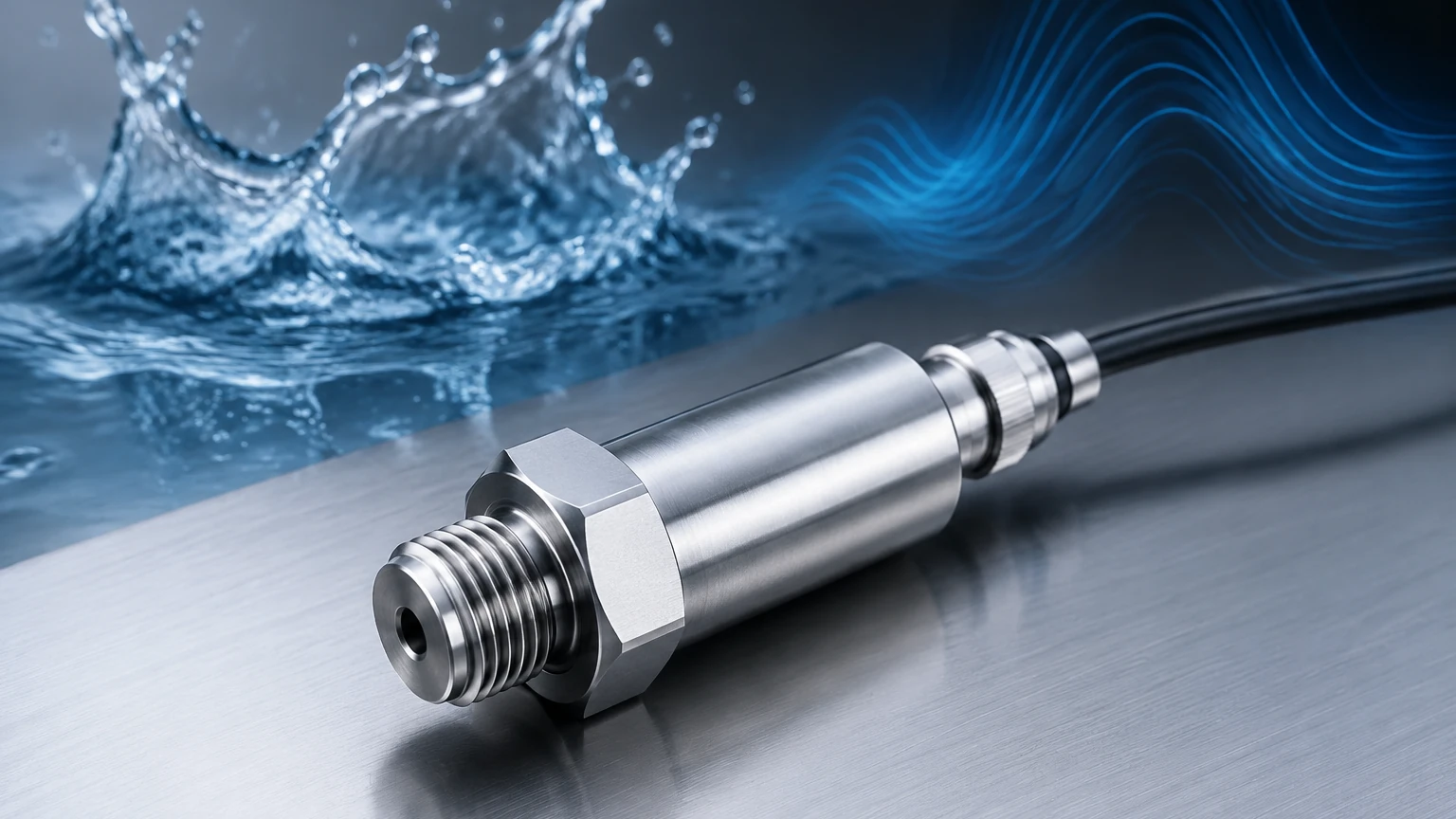
In the realm of industrial automation and process control, the speed at which a system can detect and react to pressure changes is often the difference between operational efficiency and catastrophic failure. A fast response pressure transducer is a specialized sensor designed to measure rapid pressure fluctuations, transients, and high-frequency dynamic events that standard sensors might miss due to mechanical or electronic damping. Whether monitoring water hammer in a treatment plant, combustion cycles in an engine, or rapid level changes in a pressurized chemical reactor, understanding the mechanics and selection criteria of these high-speed instruments is essential for modern engineering.
Measurement Principles of High-Speed Pressure Transducers
To appreciate why a fast response pressure transducer is necessary, one must first understand the underlying physics of pressure sensing. Most industrial transducers convert mechanical force into an electrical signal using a sensing element. However, the "speed" or response time of the sensor is dictated by its natural frequency and the damping characteristics of the internal architecture.
Piezoresistive Technology
One of the most common technologies for fast-response applications is the piezoresistive strain gauge. These sensors typically utilize a silicon diaphragm with integrated resistors. When pressure is applied, the diaphragm deforms, changing the electrical resistance. Because silicon is highly elastic and has a very low mass, these sensors can achieve high natural frequencies, often in the range of several hundred kilohertz (kHz). This allows them to capture pressure rises occurring in microseconds.
Piezoelectric Technology
For the fastest possible response—specifically for capturing shock waves or blast pressures—piezoelectric transducers are often preferred. These utilize crystals (like quartz) or ceramic materials that generate an electric charge when mechanically stressed. Unlike piezoresistive sensors, piezoelectric sensors are primarily used for dynamic pressure measurement rather than static pressure, as the charge eventually leaks away. Their response times are exceptionally fast, often measured in the nanosecond to microsecond range.
Thin-Film Technology
Thin-film transducers involve sputtering a strain gauge onto a stainless steel diaphragm. While generally more robust and resistant to high temperatures than silicon-based sensors, they often have a slightly lower frequency response due to the higher mass of the metal diaphragm. However, they remain a staple in industrial hydraulic systems where durability and speed must be balanced.
Key Evaluation Criteria for B2B Procurement
When selecting a fast response pressure transducer for industrial applications, engineers must look beyond the standard pressure range and accuracy. The following technical specifications are critical for high-speed data acquisition.
Frequency Response and Natural Frequency
The frequency response indicates the range of frequencies over which the transducer can accurately measure pressure. As a rule of thumb, to avoid resonance issues, the natural frequency of the sensor should be at least five to ten times higher than the highest frequency component of the pressure signal being measured.
Rise Time
Rise time is the interval required for the transducer output to change from 10% to 90% of its final value in response to a step change in pressure. In high-speed applications, such as valve switching or explosive testing, a rise time of less than 1 millisecond (ms) or even 1 microsecond (µs) may be required.
Sampling Rate and Signal Conditioning
A fast sensor is useless if the data acquisition system cannot keep up. The electronic output (typically 4-20mA, 0-10V, or digital protocols like RS485) must have a high enough bandwidth. For truly fast response, analog voltage outputs are often preferred over processed digital signals, as the latter may introduce latency through Analog-to-Digital (ADC) conversion and filtering.
Practical Selection Table for Industrial Applications
The following table provides a comparison of common technologies used in fast-response scenarios to assist in the initial selection process.
| Technology | Typical Response Time | Best For | Limitations |
| :— | :— | :— | :— |
| Piezoresistive (Silicon) | < 1 ms | General industrial, hydraulics, level | Temperature sensitivity |
| Piezoelectric | < 1 µs | Shock waves, combustion, blasts | Cannot measure static pressure |
| Thin-Film | 1 – 5 ms | Heavy machinery, high vibration | Lower frequency ceiling |
| Capacitive | 10 – 50 ms | Precision HVAC, low pressure | Too slow for dynamic transients |
Installation Considerations for Dynamic Accuracy
The physical installation of a fast response pressure transducer is just as important as the sensor's internal specifications. Improper mounting can introduce "dead volume" or mechanical damping that artificially slows down the recorded response.
1. Minimize Dead Volume: Any cavity or tubing between the pressure source and the sensor diaphragm acts as a pneumatic or hydraulic filter. This is known as the "Helmholtz resonance" effect. For the fastest response, flush-diaphragm mounting is recommended, where the sensor face is directly in contact with the process media.
2. Mounting Torque: Over-tightening a transducer can introduce mechanical stress into the diaphragm, shifting the zero point or altering the frequency response. Always follow the manufacturer’s torque specifications.
3. Cable Length and Shielding: High-speed signals are susceptible to electromagnetic interference (EMI). Use shielded twisted-pair cables and keep cable runs as short as possible to minimize capacitance, which can roll off high-frequency signal components.
4. Thermal Protection: Rapid pressure changes are often accompanied by rapid temperature changes (adiabatic heating). If the sensor is not thermally compensated or protected by a thin coating, the resulting thermal shift can be mistaken for a pressure change.
Limitations and Common Risks
While fast response pressure transducers are powerful tools, they are not without their drawbacks. Engineers should be aware of the following risks when integrating these sensors into a system:
* Fatigue Life: Sensors subjected to constant high-frequency pressure cycles (millions of cycles per day) are prone to mechanical fatigue. It is essential to select a sensor with a high overpressure rating and a robust diaphragm material.
* Signal Noise: High-bandwidth sensors capture everything, including pump vibration and electrical noise. Sophisticated filtering may be required at the controller level to distinguish between a true pressure spike and system noise.
* Cost vs. Performance: High-frequency sensors often require specialized materials and calibration. For many standard level measurement applications, a standard transmitter may suffice. It is important to define whether the application truly requires sub-millisecond response before investing in high-end dynamic sensors.
Frequently Asked Questions (FAQs)
Q: Can a fast response pressure transducer be used for hydrostatic level measurement?
A: Yes, especially in tanks where the level changes rapidly or where there is significant turbulence. However, for most steady-state level applications, a standard hydrostatic transmitter is more cost-effective. For more information on various level measurement technologies, you can visit the Main Page.
Q: What units are typically used for high-speed pressure measurement?
A: In industrial contexts, the metric system is standard, with measurements in bar or kilopascals (kPa). In the United States, pounds per square inch (psi) is still widely used. 1 bar is approximately equal to 14.5 psi.
Q: Does the media (liquid vs. gas) affect the response time?
A: Absolutely. Liquids are nearly incompressible, meaning pressure waves travel much faster through them than through gases. In gas applications, the "speed of sound" in the specific gas limits how fast a pressure change can reach the sensor.
Q: How often should these sensors be calibrated?
A: Because they are often used in critical or high-stress environments, annual calibration is a standard recommendation. If the sensor is subjected to frequent pressure shocks, semi-annual checks may be necessary to ensure the diaphragm hasn't suffered from permanent deformation or "zero drift."
Conclusion and Next Steps
Selecting the right fast response pressure transducer requires a deep understanding of the dynamic nature of your process. By prioritizing natural frequency, minimizing installation dead volume, and choosing the appropriate sensing technology—be it piezoresistive for versatile industrial use or piezoelectric for extreme transients—engineers can ensure their systems remain safe and optimized.
Before finalizing a purchase, it is critical to confirm the required sampling rate of your data acquisition system and the compatibility of the sensor’s wetted materials with your process media. For those seeking reliable, accurate, and cost-effective measurement solutions across water treatment, chemical, or oil and gas industries, reviewing a comprehensive range of industrial instruments is the best way to ensure application success. For a broader look at available measurement technologies and expert support, please refer to the Main Page to explore product options tailored to your specific industrial needs.