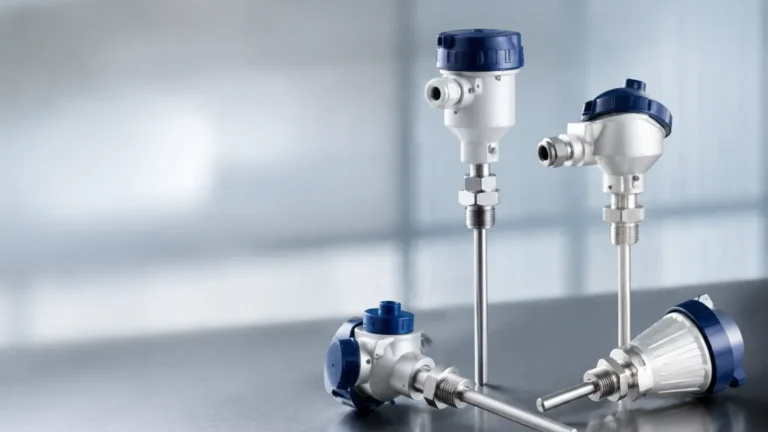
Carotek Matthews
Carotek Matthews
In the landscape of industrial process control and automation, regional centers of excellence play a pivotal role in bridging the gap between advanced manufacturing and on-site application. Carotek, headquartered in Matthews, North Carolina, represents a significant hub for technical distribution and engineering services in the Southeast United States. For process engineers and procurement specialists, understanding the synergy between high-quality instrumentation manufacturers, such as Welk, and localized technical support is essential for maintaining operational efficiency and safety.
Level measurement is a fundamental requirement across industries ranging from municipal water treatment to complex chemical processing. Selecting the appropriate technology requires a deep dive into the physics of measurement, the characteristics of the media, and the physical constraints of the vessel. When beginning the procurement process, reviewing a comprehensive Main Page of instrumentation options allows engineers to compare the specifications of radar, ultrasonic, and hydrostatic sensors against their specific project requirements.
Principles of Industrial Level Measurement
Before selecting a device, it is critical to understand the underlying principles that govern different measurement technologies. Each method has distinct advantages and limitations based on the physical properties of the liquid or solid being measured.
1. Radar Level Measurement (Non-Contact)
Radar level meters operate on the Time-of-Flight (ToF) principle. The sensor emits a high-frequency microwave signal (typically in the 26 GHz or 80 GHz range) that travels to the surface of the product, reflects, and returns to the sensor antenna. Since microwaves travel at the speed of light, the distance is calculated based on the time interval between emission and reception.
* Key Factor: Dielectric Constant ($ε_r$). The ability of a material to reflect radar waves depends on its dielectric constant. Materials with high $ε_r$, such as water, provide strong reflections. Low $ε_r$ materials, like oils or plastic pellets, may require more sensitive high-frequency (80 GHz) radar units to ensure a reliable signal return.
2. Ultrasonic Level Measurement
Ultrasonic sensors use sound waves rather than electromagnetic waves. The transducer emits a mechanical pulse that bounces off the surface of the media. The distance is determined by the time taken for the echo to return, adjusted for the speed of sound in the specific atmosphere of the tank.
* Key Factor: Temperature and Atmosphere. Because the speed of sound varies with temperature, ultrasonic sensors must include integrated temperature compensation. Furthermore, heavy vapors, dust, or foam can absorb or scatter the sound waves, potentially leading to signal loss.
3. Hydrostatic Level Measurement
This contact-based method measures the pressure exerted by a liquid column at a specific point (usually the bottom of the tank). The pressure is directly proportional to the height of the liquid and its density, following the formula $P = ρgh$ (where $P$ is pressure, $ρ$ is density, $g$ is gravity, and $h$ is height).
* Key Factor: Constant Density. Hydrostatic measurement is highly accurate provided the density of the fluid remains constant. If the process involves significant temperature swings or chemical mixing that changes the fluid density, the level reading will require compensation.
4. Magnetic Level Gauges
Magnetic level gauges utilize a float containing an internal magnet assembly that moves with the liquid level in a bypass chamber. This magnet interacts with an external indicator (flaps or a tracker) and can be paired with a reed-chain transmitter for remote signal output.
* Key Factor: Buoyancy and Pressure. The float must be engineered to the specific gravity of the liquid to ensure it sits correctly at the surface. These systems are favored for high-pressure or high-temperature applications where glass gauges would be unsafe.
Technology Selection Table
Choosing the right instrument involves evaluating the process environment. The following table provides a general comparison of common technologies used in industrial applications.
| Technology | Typical Range | Accuracy | Media Type | Key Limitation |
| :— | :— | :— | :— | :— |
| 80 GHz Radar | Up to 120m | ±1mm | Liquids & Solids | Extremely low dielectric materials |
| Ultrasonic | 0.25m – 15m | ±0.25% | Water/Wastewater | Foam, vacuum, or high dust |
| Hydrostatic | 1m – 200m | ±0.1% – 0.5% | Liquids | Changing fluid density |
| Magnetic Gauge | 0.3m – 6m | ±5mm – 10mm | Clean Liquids | Viscous or coating fluids |
Practical Selection Criteria
When working with technical partners like those found in the Carotek Matthews region, the selection process usually begins with a detailed application data sheet. Engineers must confirm the following parameters:
1. Process Temperature and Pressure: Standard ultrasonic sensors are often limited to 80°C (176°F) and atmospheric pressure. For high-pressure boilers or cryogenic storage, radar or magnetic gauges with specialized housings are required.
2. Chemical Compatibility: The wetted parts of the sensor (e.g., 316L stainless steel, PTFE, PVDF, or Hastelloy) must be resistant to the process media. This is particularly critical for hydrostatic transmitters submerged in corrosive acids.
3. Vessel Geometry: Internal obstructions such as agitators, heating coils, or ladders can create "false echoes" for radar and ultrasonic sensors. Modern sensors include software for "false signal suppression," but physical placement remains the first line of defense.
4. Measurement Goal: Is the requirement for continuous level monitoring (4-20mA/HART output) or simple point level detection (high/low alarms)? Point level switches, such as tuning forks or capacitive probes, are often used as redundant safety backups for continuous transmitters.
Installation and Engineering Considerations
Proper installation is as important as the technology itself. Even the most advanced radar meter will fail if installed incorrectly. In the industrial corridors of North Carolina and beyond, technical support teams emphasize the following installation best practices:
Nozzle Design and Placement
For non-contact sensors (Radar/Ultrasonic), the sensor should be mounted away from the tank wall to avoid interference. A general rule is to maintain a distance from the wall equal to 1/6th of the tank diameter. Additionally, the sensor should not be mounted directly above the fill stream, as the turbulence and falling material will cause erratic readings.
Dead Zones (Blocking Distance)
Every ultrasonic and radar sensor has a "dead zone" or "blocking distance" directly below the sensor face (typically 0.1m to 0.5m depending on the frequency). The maximum liquid level must never enter this zone, or the sensor will lose its ability to process the return signal. If a tank must be filled to the absolute top, a nozzle extension or a different technology may be necessary.
Venting and Condensation
In humid environments or applications involving warm liquids, condensation can form on the sensor face. While many modern radar antennas are designed with convex PTFE covers to shed droplets, ultrasonic sensors may struggle with heavy condensation. Ensuring proper tank venting can mitigate these effects.

The Value of Regional Technical Support
The presence of engineering firms and distributors in Matthews, NC, provides local industries with several advantages. When dealing with complex level measurement challenges, having access to local inventory and field service technicians ensures that downtime is minimized.
Regional experts provide:
* On-site Troubleshooting: Identifying interference issues that may not be apparent in a technical manual.
* Calibration Services: Ensuring that hydrostatic and magnetic systems are calibrated to the specific gravity of the actual process fluid.
* Integration Support: Assisting in the communication setup between the field instrument and the central PLC/SCADA system using protocols like Modbus, Profibus, or HART.
Limitations and Common Risks
While modern instrumentation is highly robust, certain conditions present ongoing challenges:
* Interface Measurement: Measuring the boundary between two liquids (e.g., oil and water) requires specialized guided wave radar (GWR) or specific gravity-based magnetic floats. Standard non-contact radar typically only sees the top surface.
* Heavy Foam: Foam acts as an insulator for ultrasonic waves and can scatter radar signals. In such cases, a stilling well or a contact-based technology like a magnetic level gauge is often the more reliable choice.
* Vacuum Conditions: Ultrasonic waves cannot travel in a vacuum. For vacuum distillation columns, radar (which uses electromagnetic waves) or hydrostatic pressure sensors are mandatory.
Frequently Asked Questions (FAQ)
Q: How often should level meters be calibrated?
A: For most industrial applications, an annual calibration check is recommended. However, in regulated industries like pharmaceuticals or municipal water billing, semi-annual calibration may be required to maintain compliance.
Q: Can radar level meters measure dry solids like grain or plastic pellets?
A: Yes. However, solids often have an uneven surface (angle of repose) and lower dielectric constants. 80 GHz radar is preferred for solids because its narrow beam angle can better target the material and handle the dust generated during filling.
Q: What is the advantage of 80 GHz radar over 26 GHz?
A: 80 GHz radar has a much narrower beam angle (as small as 3 degrees). This allows it to be installed in smaller nozzles and avoid internal tank obstructions like agitators more effectively than 26 GHz models.
Q: Is hydrostatic measurement suitable for pressurized tanks?
A: Standard hydrostatic measurement assumes the tank is vented to the atmosphere. For pressurized tanks, a differential pressure (DP) transmitter must be used. One side measures the liquid + headspace pressure, while the other side measures only the headspace pressure; the transmitter then calculates the difference to determine the liquid level.
For engineers seeking to optimize their process loops, the combination of high-performance hardware from manufacturers and the localized engineering expertise found in hubs like Carotek Matthews ensures a reliable solution. For a detailed look at specific product specifications and application engineering data, visiting the Main Page is the recommended next step in the technical evaluation process.