Field Mag Meter
Field Mag Meter
In the landscape of industrial process control, the electromagnetic flow meter—often referred to in the industry as a field mag meter—stands as a cornerstone technology for measuring the volumetric flow of conductive liquids. Unlike mechanical flow meters that rely on moving parts, the mag meter utilizes electromagnetic properties to provide highly accurate, obstruction-free measurements. This article provides a comprehensive engineering reference for selecting, installing, and maintaining field mag meters within industrial environments, ranging from water treatment to chemical processing.
Measurement Principles of the Field Mag Meter
The operation of a field mag meter is based on Faraday’s Law of Electromagnetic Induction. This principle states that a voltage is induced when a conductive medium moves through a magnetic field. In the context of a flow meter, the liquid serves as the conductor, and the meter body provides the magnetic field.
Faraday’s Law in Practice
The fundamental equation governing the measurement is:
E = B × v × D
Where:
* E is the induced voltage (Electromotive Force).
* B is the magnetic field strength generated by the internal coils.
* v is the average velocity of the conductive liquid.
* D is the conductor width, which corresponds to the internal diameter of the meter pipe.
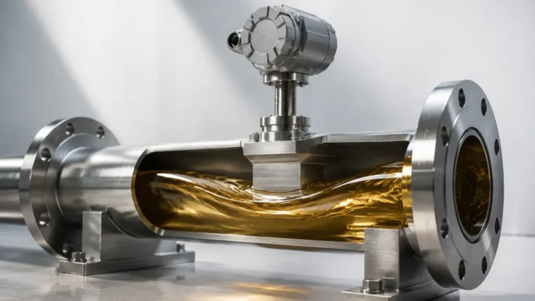
When the liquid flows through the pipe, the magnetic field (generated by copper coils energized by an electrical current) is perpendicular to the direction of flow. As the conductive liquid passes through this field, a voltage is induced. This voltage is captured by two electrodes mounted on opposite sides of the pipe wall. Because the magnetic field strength (B) and the pipe diameter (D) are constants for a specific meter, the induced voltage (E) is directly proportional to the flow velocity (v). The transmitter then converts this micro-voltage signal into a standard industrial output, such as 4-20mA, pulse, or digital protocols like Modbus or HART.
Conductivity Requirements
For a field mag meter to function, the fluid must have a minimum level of electrical conductivity. Generally, most industrial mag meters require a conductivity of at least 5 μS/cm (microsiemens per centimeter). This makes the technology ideal for water, acids, bases, and slurries, but unsuitable for hydrocarbons, distilled water, or non-polar solvents which lack the necessary ions to induce a voltage.
Key Components and Construction
Understanding the construction of a field mag meter is essential for proper selection, as the materials must be compatible with the process fluid.
1. The Flow Tube: Typically constructed from non-magnetic stainless steel to prevent interference with the magnetic field.
2. The Liner: Since the flow tube is metal, an insulating liner is required to prevent the induced voltage from shorting out to the pipe wall. Common materials include PTFE (Teflon), PFA, Neoprene, and Hard Rubber.
3. Electrodes: These are the sensors that contact the fluid. They must be resistant to corrosion and abrasion. Standard materials include Stainless Steel 316L, Hastelloy C, Tantalum, and Titanium.
4. Excitation Coils: These generate the magnetic field. Modern meters typically use pulsed DC excitation to reduce noise and improve zero-point stability.
5. The Transmitter: This is the "brain" of the unit, which can be mounted directly on the sensor (compact type) or remotely (remote type) via a signal cable.
Practical Selection Criteria
Choosing the right field mag meter requires a detailed analysis of the process conditions. Engineers must balance chemical compatibility with physical durability.
Liner Selection Table
| Liner Material | Temperature Range | Characteristics | Common Applications |
| :— | :— | :— | :— |
| PTFE (Teflon) | -40°C to +180°C | Excellent chemical resistance, anti-adhesive. | Strong acids, bases, high-temp chemicals. |
| PFA | -40°C to +180°C | Similar to PTFE but better vacuum resistance. | Food and Beverage, high-purity chemicals. |
| Neoprene | -20°C to +60°C | Good abrasion resistance. | Wastewater, low-concentration slurries. |
| Hard Rubber | 0°C to +80°C | High durability and impact resistance. | General water service, cooling water. |
| Polyurethane | -20°C to +50°C | Superior abrasion resistance. | Mining slurries, sand-laden water. |
Electrode Material Selection
* Stainless Steel 316L: Suitable for water, wastewater, and mildly corrosive liquids.
* Hastelloy C: Required for sea water and various salt solutions.
* Titanium: Used for chloride-rich environments where stainless steel would pit.
* Tantalum: Reserved for highly aggressive acids like hydrochloric or sulfuric acid.
* Platinum/Iridium: Used for extremely corrosive or high-purity pharmaceutical applications.
Installation Considerations for Field Mag Meters
To ensure the accuracy specified by the manufacturer (often ±0.5% or better), the field mag meter must be installed according to strict hydraulic guidelines.
Pipe Orientation and Filling
The most critical requirement for a mag meter is that the pipe must be completely full of liquid. If the pipe is partially full, the meter will over-calculate or under-calculate the flow, or fail to provide a reading entirely.
* Vertical Installation: Flowing upwards is the preferred orientation. This ensures the pipe remains full and prevents air bubbles from collecting at the electrodes.
* Horizontal Installation: The meter should be placed at a low point in the piping system. The electrodes should be oriented horizontally (at the 3 o'clock and 9 o'clock positions) to prevent interference from air bubbles at the top or sediment at the bottom.
Straight Pipe Runs
Turbulence caused by valves, pumps, or elbows can distort the flow profile. To achieve a stable reading, a field mag meter typically requires a straight run of pipe equal to 5 times the nominal diameter (5D) upstream and 3 times the diameter (3D) downstream. If high-performance flow conditioners are used, these requirements may be reduced, but 5D/3D remains the industry standard for field installations.
Grounding and Electrical Noise
Because the signal generated by a mag meter is in the millivolt range, it is highly susceptible to electrical noise. Proper grounding is mandatory.
* Conductive Pipes: The meter should be bonded to the metal piping.
* Non-Conductive (Plastic) Pipes: Grounding rings must be installed between the meter flange and the pipe flange to provide a path to the fluid and stabilize the reference potential.

Limitations and Common Risks
While highly versatile, the field mag meter is not a universal solution. Engineers should be aware of the following limitations:
* Non-Conductive Fluids: As mentioned, oils, diesel, and deionized water cannot be measured. For these applications, ultrasonic or Coriolis meters are typically preferred.
* Vacuum Conditions: Some liners, particularly PTFE, can collapse or peel away from the tube wall under vacuum conditions. If the process involves vacuum, a PFA liner with a reinforced mesh is usually required.
* Flow Profile Sensitivity: While more robust than turbine meters, significant swirl or non-uniform flow profiles can still introduce errors.
* Coating and Scaling: If the fluid is prone to leaving deposits (like calcium carbonate or heavy oils), the electrodes may become insulated from the fluid. Some field mag meters include an electrode cleaning circuit or "empty pipe detection" to mitigate these risks.
Integration with Industrial Automation
In modern industrial facilities, flow data is rarely used in isolation. It is frequently integrated with level measurement systems to provide a complete picture of mass balance and inventory. For instance, in a chemical storage tank, the level sensor monitors the volume in the tank while the field mag meter monitors the rate of discharge.
For engineers looking to optimize their measurement loops, it is beneficial to Review product options and application support on the Main Page to ensure that the chosen instrumentation—whether for flow or level—is compatible with the specific environmental and chemical demands of the site.
Frequently Asked Questions (FAQ)
Q: Can a field mag meter measure gas or steam?
No. Gases and steam are non-conductive and do not have the density required to induce a measurable voltage in an electromagnetic field. Vortex or thermal mass meters are used for these applications.
Q: How often does a mag meter need calibration?
Because there are no moving parts to wear down, mag meters are extremely stable. In many water applications, a "wet calibration" is only required every 3 to 5 years, though many industries perform annual electronic verification of the transmitter.
Q: What happens if the fluid contains solids?
Mag meters are excellent for slurries. However, high concentrations of abrasive solids (like sand or ore) will eventually wear down the liner. In these cases, choosing a Polyurethane or Ceramic liner is essential for long-term reliability.
Q: Does the viscosity of the liquid affect accuracy?
Generally, no. As long as the flow is turbulent and the liquid is conductive, the field mag meter is independent of viscosity, density, and pressure changes.
Conclusion
The field mag meter remains one of the most reliable and low-maintenance tools in the instrumentation engineer's toolkit. By understanding the underlying physics of Faraday’s Law and carefully selecting materials that match the process chemistry, users can achieve high-precision flow measurement with minimal downtime. Whether managing wastewater discharge or controlling precise chemical dosing, the mag meter provides the data necessary for efficient, automated industrial operations. For further technical specifications and to explore a full range of industrial measurement solutions, visit the Main Page.