Flow Gage
Flow Gage
In industrial process control, a flow gage (often spelled flow gauge) is a critical instrument used to measure the volume or mass of a fluid—liquid or gas—passing through a specific point in a system per unit of time. While level measurement focuses on the quantity of material stored within a vessel, flow measurement addresses the dynamics of material movement. Accurate flow data is essential for billing, process efficiency, chemical dosing, and safety monitoring across industries such as water treatment, oil and gas, and chemical processing.
Understanding the specific requirements of an application is the first step in selecting the correct flow gage. This guide explores the fundamental principles of flow measurement, provides selection criteria, and details the installation practices necessary to ensure long-term accuracy and reliability.
Fundamental Principles of Flow Measurement
Flow measurement technologies are categorized based on the physical principles they employ to derive flow rates. In industrial settings, the most common methods include differential pressure, velocity-based measurement, and level-to-flow conversion for open channels.
Differential Pressure (DP)
Differential pressure meters operate on Bernoulli’s principle, which states that as the speed of a moving fluid increases, the pressure within the fluid decreases. By placing a restriction in a pipe—such as an orifice plate, Venturi tube, or nozzle—a pressure drop is created. The square root of the pressure difference between the upstream and downstream sides of the restriction is proportional to the flow rate. While robust, these gages often introduce a permanent pressure loss into the system.
Velocity-Based Measurement
Velocity-based flow gages measure the speed of the fluid at one or more points and calculate the volumetric flow rate based on the cross-sectional area of the pipe ($Q = A \times v$).
* Ultrasonic Flow Gages: These use sound waves to determine velocity. Transit-time ultrasonic meters send pulses back and forth across the stream; the difference in time taken for the signal to travel with the flow versus against it reveals the velocity. Doppler ultrasonic meters reflect sound off particles or bubbles in the fluid to measure frequency shifts.
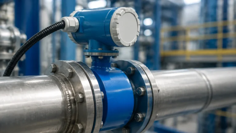
* Electromagnetic Flow Gages: Based on Faraday’s Law of Induction, these meters are used for conductive liquids. As a conductive fluid moves through a magnetic field generated by the meter, it produces a voltage proportional to its velocity.
* Radar Flow Gages: Often used in non-contact applications, radar sensors measure the surface velocity of a liquid. When combined with level data, they provide a comprehensive flow profile for open channels or partially filled pipes.
Level-to-Flow Conversion (Open Channel)
In open-channel environments like irrigation canals or wastewater treatment plants, flow is often measured by monitoring the liquid level (head) behind a primary device, such as a weir or flume. Because the geometry of the weir or flume is known, the flow rate can be calculated using standardized mathematical formulas. High-precision radar or ultrasonic level sensors are frequently deployed as the primary sensing element in these flow gage configurations.
Selection Criteria for Industrial Flow Gages
Choosing the right flow gage requires a thorough analysis of the fluid properties and the physical environment. The following table provides a comparison of common technologies used in modern industrial automation.
| Technology | Fluid Suitability | Accuracy (Typical) | Pressure Drop | Maintenance Level |
| :— | :— | :— | :— | :— |
| Differential Pressure | Clean liquids and gases | ±1.0% to ±2.0% | High | Medium |
| Electromagnetic | Conductive liquids/slurries | ±0.2% to ±0.5% | Negligible | Low |
| Ultrasonic (Transit-time) | Clean liquids | ±0.5% to ±1.0% | None | Low |
| Radar (Open Channel) | Any liquid surface | ±1.0% to ±3.0% | None | Very Low |
| Thermal Mass | Gases | ±1.0% | Low | Medium |
Key Evaluation Factors
1. Fluid Composition: Is the fluid corrosive, abrasive, or viscous? For example, electromagnetic meters are ideal for slurries, whereas ultrasonic transit-time meters require clean fluids to prevent signal scattering.
2. Flow Range (Turndown Ratio): This is the ratio between the maximum and minimum flow rates the gage can accurately measure. A high turndown ratio is necessary for processes with significant seasonal or operational fluctuations.
3. Conductivity: Only conductive fluids (typically >5 μS/cm) can be measured with magnetic flow gages.
4. Installation Footprint: Some technologies require long straight runs of pipe to stabilize the flow profile, while others, like certain ultrasonic configurations, are more forgiving of tight spaces.
For engineers seeking specific instrument specifications and technical support, it is advisable to Review product options and application support to ensure the selected hardware aligns with the site’s hydraulic profile.
Installation Considerations and Best Practices
Even the most advanced flow gage will fail to deliver accurate results if installed incorrectly. Proper placement is the single most important factor in achieving specified performance.
Straight Pipe Requirements
Most flow gages require a "developed flow profile" to measure accurately. Turbulence caused by elbows, valves, pumps, or reducers can create swirls and non-uniform velocity profiles. As a general rule, a flow gage should have at least 10 diameters (10D) of straight pipe upstream and 5 diameters (5D) downstream. If these distances cannot be met, flow straighteners or vanes may be required.
Pipe Orientation and Filling
For liquid applications, the pipe must be completely full at the point of measurement. If air pockets form at the top of the pipe or sediment settles at the bottom, the cross-sectional area calculation will be incorrect, leading to significant errors.
* Vertical Upward Flow: This is often the preferred orientation for liquids as it ensures the pipe remains full.
* Horizontal Flow: The sensor should be installed at a low point in the piping system to prevent air entrapment.
Grounding and Shielding
Electronic flow gages, particularly electromagnetic types, are sensitive to electrical noise. Proper grounding to the process fluid is essential to prevent stray currents from interfering with the low-voltage signals generated by the sensor. Using shielded cables and ensuring they are separated from high-voltage power lines is a standard requirement for industrial reliability.

Limitations and Common Risks
While modern flow gages are highly sophisticated, they are not immune to environmental and process-related challenges.
* Entrained Air: In ultrasonic and magnetic meters, air bubbles can attenuate signals or cause erratic readings. In volumetric meters, air is measured as fluid, leading to over-reporting of flow rates.
* Scaling and Coating: In chemical or wastewater applications, the build-up of minerals or biological film on the sensor electrodes or inner pipe walls can change the pipe diameter or insulate the sensors, leading to drift.
* Vibration: High-frequency vibration from nearby machinery can interfere with the sensitive electronics of vortex or ultrasonic meters. Dampening mounts may be necessary in heavy industrial environments.
* Temperature Extremes: Rapid changes in fluid temperature can affect the density and viscosity of the fluid, which may require compensation in the flow computer to maintain mass-flow accuracy.
The Role of Level Measurement in Flow Calculation
In many B2B applications, particularly in water management and environmental monitoring, a "flow gage" is actually a level measurement system in disguise. By using non-contact radar or ultrasonic level transmitters, operators can monitor the flow in open channels without ever touching the fluid. This approach is highly valued because it eliminates the risk of sensor fouling and reduces maintenance costs.
When a level sensor is used as a flow gage, it measures the height of the liquid in a flume. The internal software of the transmitter then applies the relevant hydraulic equation (e.g., the Manning equation or specific flume coefficients) to output a real-time flow rate in cubic meters per hour (m³/h) or liters per second (L/s). This integration highlights the synergy between level and flow technologies in modern industrial automation.
Frequently Asked Questions (FAQ)
Q: How often should a flow gage be calibrated?
A: Calibration frequency depends on the criticality of the measurement and the harshness of the environment. For billing or regulatory compliance, annual calibration is standard. For process monitoring, a biennial verification may suffice.
Q: Can a flow gage measure both directions of flow?
A: Many modern electronic gages, such as electromagnetic and ultrasonic meters, are inherently bi-directional. However, they must be configured in the software to track and totalize flow in both directions.
Q: What is the difference between a flow meter and a flow gage?
A: In technical terms, they are often used interchangeably. However, a "gage" sometimes refers to the local display or the physical sensing component, while a "meter" refers to the entire system, including the transmitter and signal processor.
Q: Why is my ultrasonic flow gage giving inconsistent readings?
A: This is most commonly caused by insufficient straight pipe runs, the presence of air bubbles, or a fluid that is too acoustically absorbent. Ensure the pipe is full and the transducers are properly coupled to the pipe wall.
Q: Is radar or ultrasonic better for open channel flow?
A: Radar is generally superior in environments with heavy steam, foam, or fluctuating air temperatures, as radar waves are not affected by air density. Ultrasonic sensors are a cost-effective alternative for stable, outdoor environments.
For further technical documentation on integrating these sensors into your control architecture, visit the Main Page for comprehensive engineering resources.