Flow Instruments
Flow Instruments
In the landscape of industrial process control, flow instruments serve as the primary sensory organs for monitoring the movement of liquids, gases, and steam through piping systems. Accurate flow measurement is essential not only for billing and custody transfer but also for maintaining the mass balance of a facility. While level measurement provides a snapshot of the current inventory within a vessel, flow instrumentation tracks the rate of change, offering a dynamic view of process efficiency. For engineers and plant managers, understanding the interplay between these two variables is critical for optimizing automation and ensuring safety.
Understanding Flow Measurement Principles
Before selecting a specific instrument, it is necessary to understand the physical principles that govern different measurement technologies. Flow instruments are generally categorized by the method they use to derive the flow rate.
1. Electromagnetic Flow Meters (Magmeters)
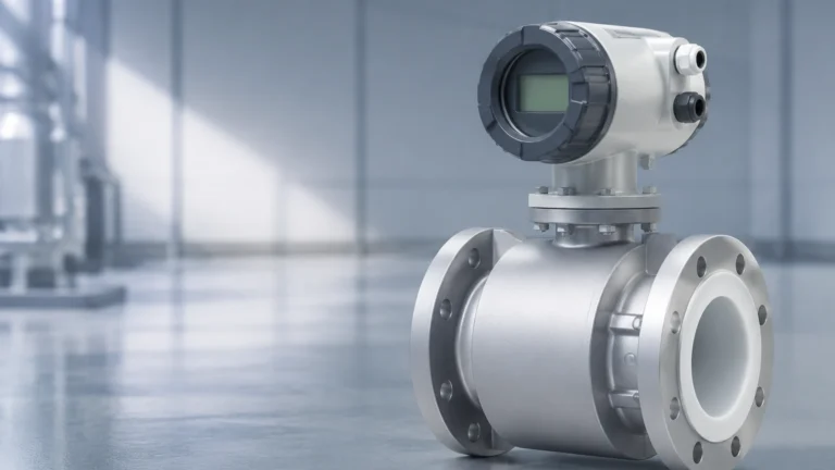
Electromagnetic flow meters operate based on Faraday’s Law of Induction. This principle states that a conductor moving through a magnetic field produces an electrical signal directly proportional to the velocity of the conductor. In this application, the conductive liquid acts as the conductor. As the fluid passes through the magnetic field generated by the meter’s coils, electrodes detect the induced voltage.
* Requirement: The fluid must have a minimum conductivity (typically >5 μS/cm).
* Advantage: No moving parts and no pressure drop.
2. Ultrasonic Flow Meters
Ultrasonic instruments use sound waves to determine fluid velocity. There are two primary types:
* Transit-Time: These meters send ultrasonic pulses back and forth across the pipe. The pulse traveling with the flow moves faster than the pulse traveling against it. The time difference is proportional to the flow velocity. These are best for clean liquids.
* Doppler: These meters reflect sound waves off particles or bubbles in the fluid. The frequency shift (Doppler effect) indicates the velocity. These are ideal for slurries or aerated liquids.
3. Differential Pressure (DP) Flow Meters
DP meters rely on Bernoulli’s equation, which describes the relationship between pressure and velocity. By placing a restriction in the pipe (such as an orifice plate, Venturi tube, or Pitot tube), a pressure drop is created. The square root of the pressure difference between the upstream and downstream points is proportional to the flow rate.
4. Vortex Shedding Flow Meters
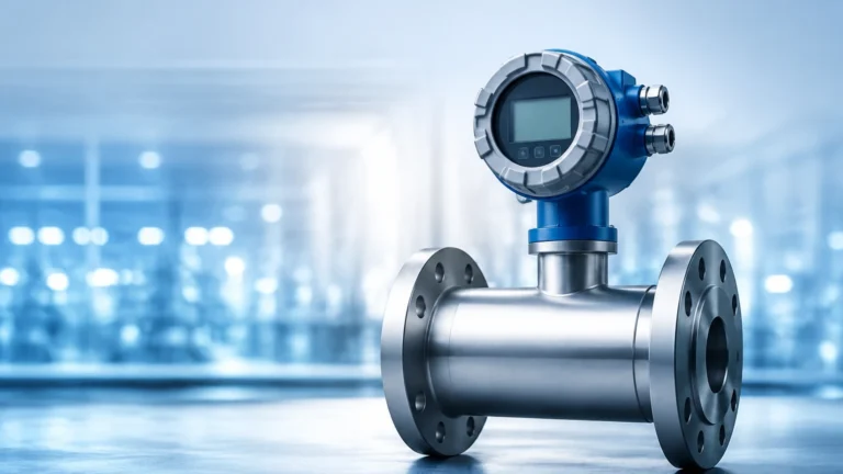
Vortex meters utilize the Von Kármán effect. When a fluid encounters a "bluff body" (a non-streamlined object), it creates alternating vortices (swirls) downstream. The frequency at which these vortices are shed is directly proportional to the velocity of the fluid. This technology is highly effective for steam and gas applications.
5. Coriolis Mass Flow Meters
Unlike the previous methods which measure volumetric flow, Coriolis meters measure mass flow directly. The fluid passes through vibrating tubes, causing a Coriolis force that twists the tubes. The degree of twist is proportional to the mass flow rate. These instruments are the most accurate but also the most capital-intensive.
The Synergy Between Flow and Level Measurement
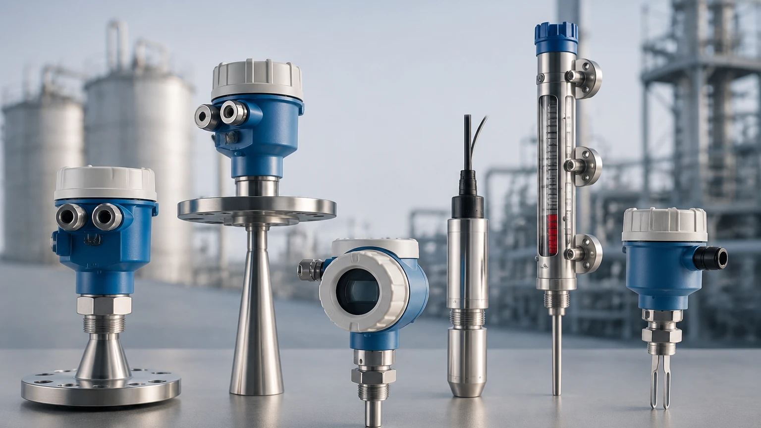
In most industrial applications, flow and level instrumentation work in tandem to provide a complete picture of the process. For instance, in a water treatment plant, a hydrostatic level transmitter might monitor the depth of a reservoir, while an electromagnetic flow meter tracks the discharge rate.
Integrating these data points allows for advanced diagnostics. If a level sensor indicates a rapid drop in a tank but the flow meter shows no discharge, it may signal a leak or a secondary unmetered outlet. Conversely, if the flow meter shows high output but the level remains static, there may be an issue with the inlet feed or the accuracy of the level instrument itself. For a comprehensive overview of how level and flow technologies integrate into industrial automation, engineers often Review product options and application support on the Welk Main Page to ensure sensor compatibility.
Key Evaluation Criteria for Flow Meter Selection
Selecting the correct flow instrument requires a detailed analysis of the process conditions. Failure to account for a single variable can lead to significant measurement errors or premature instrument failure.
* Fluid Properties: Is the fluid conductive? Does it contain solids or entrained air? What is its viscosity and density? For example, a magnetic flow meter will fail on demineralized water because the conductivity is too low.
* Pipe Specifications: The nominal diameter (DN) of the pipe and the material (e.g., carbon steel, PVC, stainless steel) dictate the mounting style. Large pipes often favor insertion-type meters or ultrasonic clamp-on models to save costs.
* Process Conditions: Maximum and minimum temperature and pressure must be within the instrument's operating envelope. High-pressure steam requires robust vortex or DP meters.
* Accuracy and Turndown Ratio: Accuracy is usually expressed as a percentage of the measured value or full scale. The turndown ratio (the range over which the meter remains accurate) is vital for processes with highly variable flow rates.
* Environmental Factors: Consider if the installation is in a hazardous area requiring ATEX or IECEx certification, or if the environment is corrosive, requiring specific housing materials like 316L stainless steel.
Technical Selection Table: Comparing Flow Technologies
| Technology | Typical Accuracy | Fluid Type | Pressure Drop | Moving Parts | Best Use Case |
| :— | :— | :— | :— | :— | :— |
| Electromagnetic | ±0.5% | Conductive Liquids | None | No | Water, Slurries, Chemicals |
| Ultrasonic | ±1.0% to 2.0% | Clean/Dirty Liquids | None | No | Retrofits, Large Pipes |
| Vortex | ±1.0% | Gas, Steam, Liquid | Medium | No | High-Temp Steam |
| Differential Pressure | ±1.0% to 3.0% | Gas, Liquid, Steam | High | No | High-Pressure Systems |
| Coriolis | ±0.1% | Liquids, Gases | Low | No | Custody Transfer, Mass Balance |
| Turbine | ±0.25% | Clean Liquids | Medium | Yes | Fuel, Oil, Clean Water |
Installation Best Practices and Considerations
Even the most expensive flow instrument will yield inaccurate data if installed incorrectly. Engineering standards emphasize several critical factors:
Straight Pipe Runs
Most flow meters require a fully developed flow profile to measure accurately. Turbulence caused by elbows, valves, or pumps can distort the profile. A general rule of thumb is to allow for 10 pipe diameters (10D) of straight pipe upstream and 5 pipe diameters (5D) downstream of the meter. If space is limited, flow conditioners (vanes) may be required.
Orientation and Filling
The pipe must be completely full of liquid for most flow meters (especially electromagnetic and ultrasonic) to function correctly. In horizontal pipes, it is best to install the meter on a slightly upward-sloping section. For vertical pipes, the flow should ideally be upward to ensure the pipe remains full and to prevent air pockets from settling at the sensor head.
Grounding and Interference
Electromagnetic flow meters are sensitive to stray electrical noise. Proper grounding to the process fluid is essential, often achieved through grounding rings if the pipe is lined or made of non-conductive material. Similarly, ultrasonic meters should be kept away from variable frequency drives (VFDs) that can cause signal interference.
Limitations and Operational Risks
Every flow measurement technology has inherent limitations that must be managed during the design phase.
* Cavitation: In liquid applications, if the pressure drops below the vapor pressure, bubbles form and collapse. This can damage the internal components of DP and turbine meters and cause significant errors in ultrasonic readings.
* Aeration: Entrained air or gas bubbles in a liquid line can cause ultrasonic signals to scatter and magmeters to read erratically. Air eliminators should be installed upstream if aeration is a known risk.
* Scaling and Coating: In chemical or wastewater applications, material can build up on the electrodes or the pipe wall. This changes the internal diameter and the electrical contact, leading to drift. Regular maintenance or the use of "self-cleaning" electrode designs is necessary.
* Viscosity Limits: Technologies like turbine meters are highly sensitive to viscosity changes. If the fluid thickens due to temperature drops, the mechanical resistance increases, leading to under-reporting of flow.
Frequently Asked Questions (FAQs)
Q: Can I use a water flow meter for oil measurement?
A: It depends on the technology. An electromagnetic flow meter will not work because oil is non-conductive. However, a Coriolis or ultrasonic (transit-time) meter can often be used, provided the viscosity is within the device's calibrated range.
Q: How often should flow instruments be calibrated?
A: For most industrial processes, an annual calibration check is standard. However, for custody transfer or high-precision chemical dosing, semi-annual or quarterly calibrations may be required by regulatory bodies or internal quality standards.
Q: What is the difference between "insertion" and "inline" flow meters?
A: Inline meters are part of the piping structure, requiring the pipe to be cut for installation; they are generally more accurate. Insertion meters are installed through a hole in the pipe (often via a hot tap) and measure velocity at a single point, making them more cost-effective for very large pipe diameters (e.g., >500 mm).
Q: How do I handle flow measurement in open channels?
A: Open channel flow, such as in wastewater effluent flumes, is typically measured using a combination of a primary device (like a Parshall flume) and a secondary level sensor (like an ultrasonic or radar level meter). The level of the liquid in the flume is converted to a flow rate using standardized formulas.
Conclusion
Flow instruments are foundational to modern industrial automation, providing the data necessary for process optimization, safety, and environmental compliance. By understanding the underlying physics—whether it be electromagnetic induction, sound wave propagation, or differential pressure—engineers can select the most robust solution for their specific application. When combined with reliable level measurement systems, such as those found on the Welk Main Page, these instruments ensure that plant operators have total visibility over their fluid assets. Proper attention to installation geometry, fluid characteristics, and potential operational risks will ensure that the flow data remains accurate and reliable over the long term.