Pressure and Temperature Transducer
Pressure and Temperature Transducer
In the landscape of industrial automation and process control, the ability to monitor multiple variables through a single point of entry is a significant advantage. A pressure and temperature transducer is a specialized instrument designed to measure both fluid pressure and the temperature of the media simultaneously. For engineers and system integrators, these dual-purpose sensors are essential for ensuring the accuracy of level measurements, protecting equipment from thermal stress, and optimizing chemical processes.
By integrating these two critical measurements into one housing, facilities can reduce the number of process penetrations, simplify wiring, and lower the total cost of ownership. This guide explores the engineering principles, selection criteria, and practical applications of these instruments within the context of modern industrial level measurement.
Understanding the Measurement Principles
To effectively select and deploy a pressure and temperature transducer, it is necessary to understand how these distinct physical properties are converted into electrical signals.
Pressure Measurement Principles
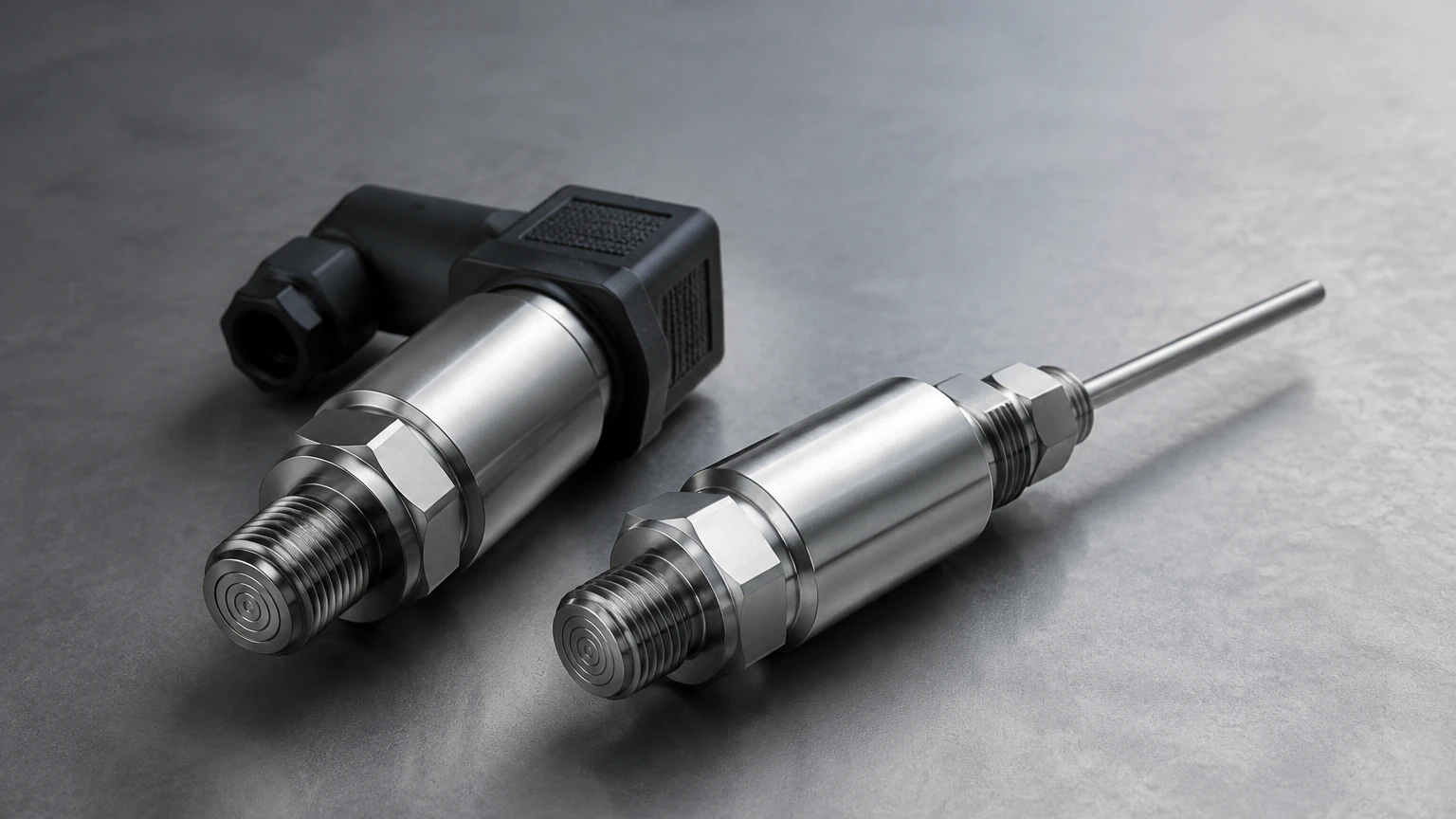
Most industrial pressure transducers utilize a sensing element—typically a piezoresistive silicon chip or a ceramic thick-film strain gauge—mounted behind a stainless steel or specialized alloy diaphragm. When the process media exerts force on the diaphragm, it deflects slightly, changing the electrical resistance of the bridge circuit. This change is proportional to the pressure.
In industrial level measurement, this is often referred to as hydrostatic pressure. The pressure at the bottom of a tank is directly related to the height of the liquid column above it, according to the formula:
*P = ρ × g × h*
(Where *P* is pressure, *ρ* is liquid density, *g* is gravity, and *h* is the height of the liquid).
Temperature Measurement Principles
Temperature sensing within these transducers is typically achieved using a Resistance Temperature Detector (RTD), most commonly a Pt100 or Pt1000 platinum element. As the temperature of the media increases, the electrical resistance of the platinum element increases in a predictable, linear fashion. Some transducers may use thermocouples for extreme temperature ranges, but RTDs are preferred in B2B industrial applications for their high stability and accuracy over time.
Signal Processing and Output
The transducer housing contains electronics that condition these raw signals. Modern units often provide dual outputs, such as two independent 4-20 mA loops, or digital communication protocols like Modbus RS485 or HART. This allows the control system to receive real-time data for both variables over a single cable run.
The Integration of Pressure and Temperature in Level Sensing
Why is the combination of these two sensors so critical in level measurement? The primary reason is density compensation.
As established in the hydrostatic pressure formula, the level calculation depends on the density (ρ) of the liquid. However, the density of most industrial fluids changes as their temperature fluctuates. For example, water at 4°C has a different density than water at 80°C. If a level transmitter assumes a constant density while the process temperature varies, the resulting level reading will be inaccurate.
By using a pressure and temperature transducer, the PLC (Programmable Logic Controller) or DCS (Distributed Control System) can use the real-time temperature data to look up the fluid's current density and apply a correction factor to the level calculation. This ensures high precision in applications like chemical dosing, fuel storage, and boiler feed-water management.
Key Evaluation Criteria for Industrial Transducers
When evaluating a pressure and temperature transducer for your project, several technical specifications must be confirmed to ensure long-term reliability.
1. Pressure Range and Overpressure Rating: Select a range where your operating pressure sits at approximately 50-70% of the full scale. Ensure the overpressure rating (the maximum pressure the unit can withstand without damage) exceeds any potential system surges.
2. Media Compatibility: The wetted parts (diaphragm and process connection) must be compatible with the fluid. While 316L stainless steel is standard, aggressive chemicals may require Hastelloy, Monel, or Tantalum coatings.
3. Accuracy Classes: Industrial transducers typically offer accuracy ranging from 0.1% to 0.5% of the full scale. For custody transfer or critical chemical reactions, higher precision models are required.
4. Temperature Limits: Confirm both the media temperature range and the ambient temperature range. High-temperature applications may require cooling fins or remote capillary seals to protect the internal electronics.
5. Ingress Protection (IP Rating): For outdoor or wash-down environments, an IP67 or IP68 rating is necessary to prevent moisture ingress into the electrical housing.
Practical Selection Table
The following table provides a general comparison of common transducer configurations found in industrial environments.
| Feature | Submersible Transducer | Threaded Process Transducer | Flanged Level Transmitter |
| :— | :— | :— | :— |
| Primary Use | Deep wells, reservoirs, open tanks | Pipelines, closed pressurized tanks | Large chemical tanks, viscous media |
| Installation | Suspended by cable | Screwed into a socket (e.g., G1/2, NPT) | Bolted to a tank nozzle |
| Pressure Range | 0 to 20 bar (typical) | 0 to 600+ bar | 0 to 40 bar |
| Temperature Range | -10°C to +70°C | -40°C to +125°C | -40°C to +150°C |
| Advantage | Easy to install in existing wells | Compact and versatile | Easier to clean; handles slurries |
Installation Guidelines and Best Practices
Proper installation is as critical as the selection of the instrument itself. Incorrect mounting can lead to signal noise, mechanical failure, or measurement drift.
* Avoid Turbulence: Do not install the transducer near tank inlets or agitators. Rapidly moving fluid can create localized pressure fluctuations that do not represent the actual liquid level.
* Orientation: For gas-containing liquids, mount the transducer so that gas bubbles cannot trap against the diaphragm. For steam applications, always use a pigtail siphon to create a liquid seal that protects the sensor from direct steam contact.
* Cable Protection: In submersible applications, the cable often contains a vent tube to compensate for atmospheric pressure changes. Ensure this vent tube is protected by a desiccant filter to prevent moisture from entering the sensor housing.
* Thermal Insulation: If the process is very hot or very cold, avoid insulating the transducer housing along with the pipe. The housing needs to dissipate heat to keep the internal electronics within their operating temperature range.
Limitations and Potential Risks
While highly versatile, a pressure and temperature transducer is not a universal solution for every application. Engineers should be aware of the following limitations:
* Vacuum Conditions: Many standard pressure diaphragms are designed for positive pressure. Exposure to a vacuum can pull the diaphragm outward, causing permanent deformation and calibration shift.
* Abrasive Solids: In mining or wastewater applications with high grit content, abrasive particles can erode the thin metal diaphragm over time, leading to sensor failure.
* Viscous and Clogging Media: Standard threaded connections have small orifices that can easily clog with thick oils, resins, or paper pulp. In these cases, a flush-diaphragm design is mandatory.
* Signal Interference: In environments with large motors or variable frequency drives (VFDs), unshielded cables can pick up electromagnetic interference (EMI). Always use high-quality shielded twisted-pair cabling and ensure proper grounding at the controller end.
Frequently Asked Questions (FAQ)
Q: Can one transducer output both signals on a single 4-20mA loop?
A: A standard 4-20mA loop can only represent one variable. To get both pressure and temperature over two wires, you must use a digital protocol like HART, which superimposes a digital signal on top of the 4-20mA analog signal, or use a device with dual 4-20mA outputs (requiring four wires).
Q: How often should these transducers be calibrated?
A: In most industrial B2B applications, annual calibration is recommended. However, if the process involves extreme temperature cycling or corrosive media, semi-annual checks may be necessary to ensure accuracy.
Q: What is the difference between gauge pressure and absolute pressure in these sensors?
A: Gauge pressure sensors are vented to the atmosphere and measure pressure relative to local barometric pressure. Absolute pressure sensors are sealed and measure relative to a perfect vacuum. For most tank level applications, gauge pressure is used.
Confirming Project Requirements
Before finalizing a purchase or specifying a model for a large-scale project, technical teams should confirm the specific environmental conditions of the site. This includes the chemical composition of the media, the presence of pressure spikes (water hammer), and the required communication protocols for the existing control architecture.
Welk provides a range of reliable, accurate, and cost-effective level measurement solutions, including radar, ultrasonic, and hydrostatic options. For detailed technical specifications and to find the right instrument for your specific industrial automation needs, you can visit the Main Page to review product options and application support. Ensuring that your pressure and temperature transducer is correctly matched to your process is the most effective way to guarantee long-term operational success.