Reflux Drum
Reflux Drum
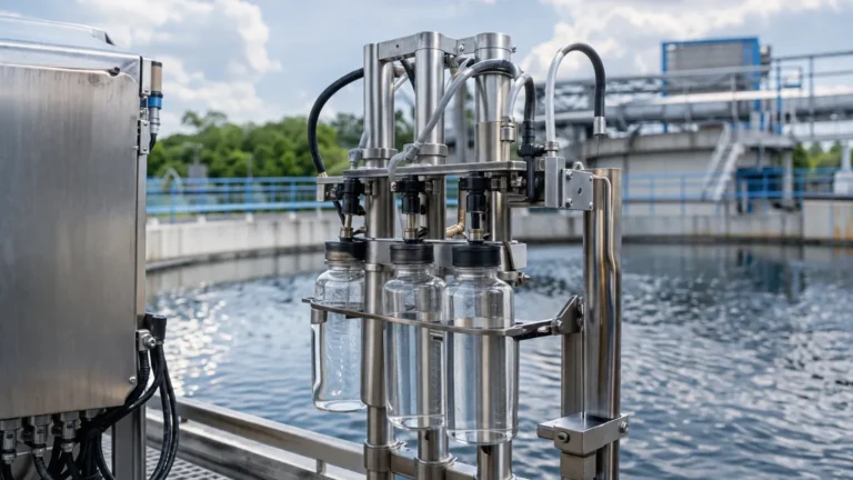
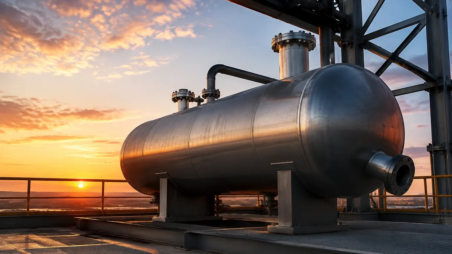
In the architecture of a distillation system, the reflux drum—often referred to as an overhead accumulator—serves as a critical buffer vessel. Its primary function is to receive the condensed overhead vapors from the distillation column, providing a surge volume that ensures a steady supply of liquid for both the reflux flow back to the column and the final distillate product. Because the stability of the entire distillation process depends on maintaining a precise mass balance, the measurement and control of the liquid level within the reflux drum are among the most vital tasks for process engineers.
Effective level management in a reflux drum prevents two major operational failures: flooding the condenser (high level) and cavitating the reflux pumps (low level). Furthermore, in many petrochemical applications, the reflux drum also acts as a decanter, where water and hydrocarbons separate based on density, requiring sophisticated interface level measurement. This guide examines the principles of level measurement technology applied to the reflux drum and provides practical selection criteria for industrial automation.
Principles of Level Measurement in Reflux Drums
Selecting the appropriate instrumentation requires an understanding of the physical principles governing the sensors. In a reflux drum environment, factors such as vapor pressure, fluid dielectric constants, and potential turbulence must be accounted for.
Guided Wave Radar (GWR)
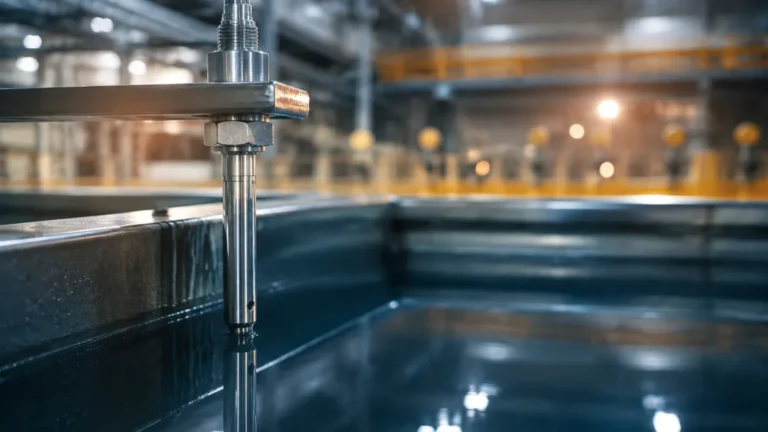
Guided Wave Radar operates on the principle of Time Domain Reflectometry (TDR). A low-energy microwave pulse is sent along a probe (the waveguide). When the pulse reaches the surface of the liquid, a portion of the energy is reflected back to the transmitter because of the change in the dielectric constant (εr) between the vapor space and the liquid.
In a reflux drum, GWR is particularly effective because it is relatively unaffected by changes in pressure or temperature. If the drum handles a mixture of hydrocarbons and water, GWR can often measure both the total level and the interface level. The pulse passes through the upper low-dielectric hydrocarbon layer (typically εr 1.9–2.5) and reflects off the high-dielectric water layer (εr ≈ 80) below.
Non-Contact Radar
Non-contact radar transmitters, specifically those operating at 80 GHz high frequencies, emit microwave signals through the air. The time-of-flight between emission and reception of the reflected signal determines the distance. The primary advantage here is the lack of physical contact with the process fluid, which reduces maintenance requirements. However, in a reflux drum with high-pressure steam or heavy vapor, signal attenuation must be considered. Modern FMCW (Frequency Modulated Continuous Wave) radar provides high resolution even in narrow nozzles.
Magnetic Level Gauges (MLG)
MLGs utilize a float containing an internal magnet assembly that moves according to the liquid level within a bypass chamber. As the float rises or falls, it rotates magnetic flags on an external scale, providing a clear visual indication. For electronic integration, a magnetostrictive transmitter can be mounted to the outside of the chamber. This technology is favored for its robustness and the fact that the visual indicator requires no power, providing a secondary safety check for operators.
Differential Pressure (DP) Transmitters
DP transmitters measure the hydrostatic head of the liquid. The pressure difference between the bottom of the drum (liquid plus vapor pressure) and the top of the drum (vapor pressure only) is proportional to the liquid height. While reliable, DP measurement is sensitive to changes in fluid density. In a reflux drum where the composition or temperature of the distillate might fluctuate, the density must be compensated for in the control system to maintain accuracy.
Key Evaluation Criteria for Reflux Drum Instrumentation
When designing the level control loop for a reflux drum, engineers must evaluate several technical parameters to ensure long-term reliability.
Dielectric Constant and Fluid Properties
Most distillates are hydrocarbons with low dielectric constants. Instruments like non-contact radar require a minimum dielectric to "see" the surface clearly. If the dielectric is extremely low (below 1.4), a guided wave radar with a coaxial probe or a stilling well is usually necessary to concentrate the signal energy.
Operating Pressure and Temperature
Reflux drums can operate under vacuum or at high pressures (exceeding 40 bar / 580 psi). The chosen instrument must have a flange rating and seal material (such as Kalrez or PTFE) capable of withstanding these conditions. High-temperature applications may require remote electronics or cooling fins to protect the transmitter head.
Interface Measurement Requirements
If the process involves a "water wash" or if steam is used in the column stripping section, the reflux drum will likely contain a water-hydrocarbon interface. Measuring the thickness of the water pad is essential for the automated drainage of the water boot. GWR is the industry standard for this application, provided there is a sufficient difference in the dielectric constants of the two liquids.
Selection Table for Level Technologies
| Technology | Accuracy | High Pressure Suitability | Interface Capable | Maintenance Level | Recommended Use Case |
| :— | :— | :— | :— | :— | :— |
| Guided Wave Radar | ±2 mm | Excellent | Yes | Low | Hydrocarbon/Water interface and low-dielectric fluids. |
| Non-Contact Radar | ±1 mm | Good | No | Very Low | Clean liquids where top-down mounting is preferred. |
| Magnetic Level Gauge | ±5 mm | Excellent | Yes (with specific floats) | Medium | Visual local indication and redundant transmission. |
| DP Transmitter | ±0.1% of span | Excellent | No | Medium | High-pressure vessels with stable fluid density. |
| Ultrasonic Sensor | ±0.25% | Poor (affected by vapor) | No | Low | Atmospheric, non-volatile water treatment tanks only. |
Installation Considerations and Best Practices
Proper installation is as critical as instrument selection. For a reflux drum, the following guidelines should be followed:
1. Nozzle Placement: The level sensor should be located away from the liquid inlet to avoid turbulence and false readings caused by the incoming stream. If the inlet is near the sensor, a stilling well or a bypass chamber (side-mounted) should be used.
2. The "Water Boot": Many horizontal reflux drums feature a smaller vertical cylinder at the bottom called a "boot." This is where the heavier water phase collects. Level sensors for the interface must be specifically calibrated for the height of this boot.
3. Bypass Chambers: For Guided Wave Radar and Magnetic Level Gauges, mounting the instrument in an external bypass chamber allows for maintenance (using isolation valves) without shutting down the distillation column. This is the preferred configuration in the oil and gas industry.
4. Venting: Ensure that the top of any bypass chamber is properly vented back to the vapor space of the reflux drum to equalize pressure. A blocked vent will lead to erroneous level readings.
5. Grounding: For radar-based systems, ensuring a proper metal-to-metal contact at the flange or using a grounding strap is essential to prevent electromagnetic interference from affecting the signal.
For engineers seeking specific hardware configurations and technical support for these applications, it is advisable to Review product options and application support to match the instrument to the specific chemical compatibility of the distillate.
Common Risks and Limitations
Despite the advanced nature of modern level sensors, certain conditions in a reflux drum can pose challenges:
* Foaming: If the distillate has a tendency to foam, non-contact radar and ultrasonic sensors may receive a diffused signal, leading to "lost echo" errors. GWR is generally more resistant to foam, as the pulse can often penetrate the foam to find the true liquid level.
* Condensation and Coating: In heavy hydrocarbon service, paraffin or bitumen can coat the probe of a GWR. While many modern transmitters have "coating rejection" algorithms, severe buildup will eventually degrade performance, requiring periodic cleaning.
* Vapor Space Attenuation: High-pressure vapors (such as high-pressure steam or heavy CO2) can slow down the speed of radar pulses. In these specific cases, a vapor compensation probe or a DP transmitter might be more reliable.
Frequently Asked Questions (FAQ)
Q: Can I use an ultrasonic sensor on a reflux drum?
A: Generally, no. Reflux drums often contain volatile organic compounds (VOCs) and operate at pressures other than atmospheric. Ultrasonic waves are affected by vapor density, temperature gradients, and pressure, making them inaccurate for most distillation applications.
Q: How do I handle level measurement if the reflux drum is horizontal?
A: Horizontal vessels have a non-linear relationship between level and volume. While the level sensor measures the height in millimeters or inches, the control system (PLC/DCS) must use a strapping table or a mathematical formula to calculate the actual volume if inventory management is required.
Q: What is the advantage of using a 80 GHz radar over a 26 GHz radar?
A: The 80 GHz radar has a much narrower beam angle. This allows it to be installed in smaller nozzles and avoids reflections from internal vessel structures like ladders or heating coils, which are common in industrial drums.
Q: Why is interface measurement important in a reflux drum?
A: If water is carried back into the distillation column with the reflux, it can cause a sudden volume expansion (steam) that may lead to a pressure surge or "puke" the column, damaging internal trays. Precise interface control allows for the continuous removal of water while retaining the valuable hydrocarbon distillate.
Conclusion
The reflux drum is a pivot point in the distillation process. Choosing the right level measurement technology—whether it be the precision of Guided Wave Radar or the ruggedness of a Magnetic Level Gauge—requires a thorough analysis of the process fluid and vessel geometry. By following standard engineering practices and considering the dielectric and pressure limitations of each technology, operators can ensure stable column operation and high-quality product separation. For further technical specifications on industrial level transmitters, visiting the Main Page provides access to comprehensive data sheets and selection guides tailored for process automation.