Flow Meter Dn150
Flow Meter Dn150
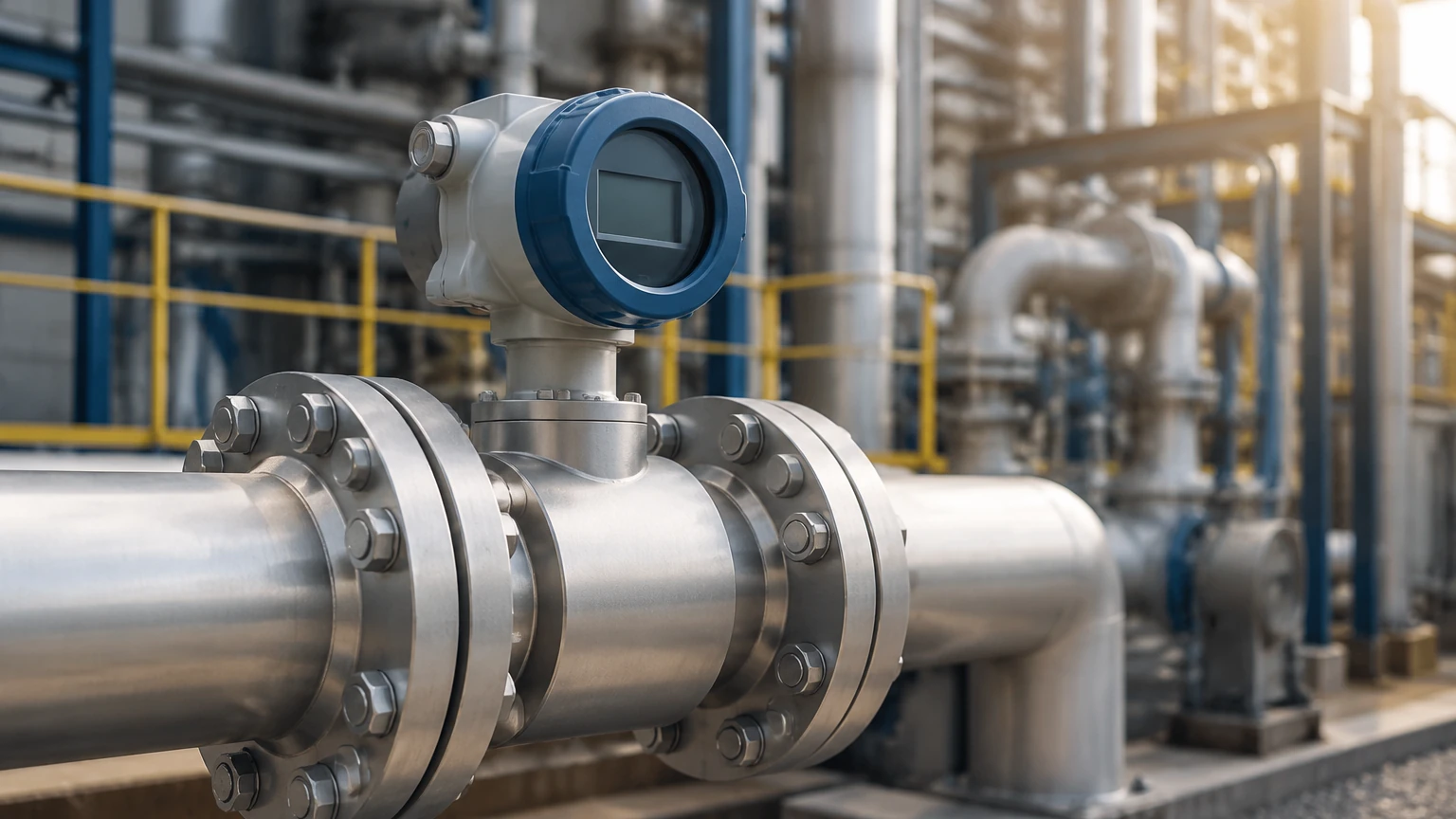
In industrial process engineering, the selection of instrumentation is dictated by pipe geometry and the physical properties of the medium. A flow meter DN150 refers to an instrument designed for a nominal diameter (Diamètre Nominal) of 150 mm, which corresponds to a 6-inch pipe size in the imperial system. This size is a critical threshold in many industries, marking the transition from secondary distribution lines to primary headers and main transport lines.
Choosing the correct flow meter DN150 requires an understanding of fluid dynamics, installation constraints, and the specific measurement principles that remain effective at this scale. Whether managing municipal water systems, chemical processing plants, or large-scale industrial automation, the DN150 size offers a balance between high volume capacity and manageable installation footprints.
Understanding the DN150 Specification
DN150 is a standard designation used in the EN 1092-1 and ISO standards to define the size of pipes, valves, and fittings. For a flow meter, the "DN150" label indicates that the internal bore of the meter is approximately 150 mm. However, the exact internal diameter (ID) can vary slightly depending on the pipe schedule or pressure rating (PN10, PN16, PN25, or PN40).
Physical Dimensions and Flow Capacity
In a standard DN150 pipe, the cross-sectional area is approximately 0.01767 square meters. This area determines the flow velocity for a given volume. For example, at a velocity of 1 meter per second (m/s), a DN150 line carries approximately 63.6 cubic meters per hour (m³/h). In industrial applications, velocities typically range from 0.5 m/s to 10 m/s for liquids, and much higher for gases or steam.
When selecting a flow meter DN150, engineers must ensure that the meter’s turndown ratio—the ratio between the maximum and minimum measurable flow—covers the operational range of the system without introducing excessive pressure drop.
Measurement Principles for DN150 Applications
Different technologies are employed to measure flow in 150 mm pipes. Each principle has distinct advantages depending on the fluid's conductivity, viscosity, and cleanliness.
Electromagnetic Flow Meters (Magmeters)
Electromagnetic flow meters operate based on Faraday’s Law of Induction. When a conductive liquid flows through a magnetic field generated by the meter, it produces a voltage proportional to its velocity.
For a DN150 application, magmeters are often the preferred choice because they have no moving parts and offer an unobstructed flow path. This results in zero pressure drop, which is vital for energy efficiency in large-diameter pumping systems. They are widely used in water treatment and chemical processing where the medium is conductive.
Ultrasonic Flow Meters
Ultrasonic meters typically use the transit-time principle. They feature pairs of transducers that send and receive ultrasonic signals through the fluid. The difference in time taken for the signal to travel upstream versus downstream is used to calculate the flow velocity.
At the DN150 scale, ultrasonic meters are available as both inline (flanged) units and clamp-on versions. Clamp-on ultrasonic meters are particularly useful for retrofitting existing 6-inch lines where cutting the pipe is not feasible. However, they require clean fluids or fluids with very low particle concentrations to maintain accuracy.
Vortex Flow Meters
Vortex meters utilize the Von Kármán effect. A bluff body (shedder bar) is placed in the flow stream, creating a series of alternating vortices. The frequency of these vortices is directly proportional to the flow velocity.
Vortex meters are highly effective for measuring steam, gases, and low-viscosity liquids in DN150 pipes. They are valued for their robustness and ability to handle high temperatures and pressures, though they do require a minimum Reynolds number to function accurately.
Turbine Flow Meters
Turbine meters use a multi-bladed rotor suspended in the flow. The fluid's movement causes the rotor to spin at a speed proportional to the flow rate. While highly accurate for clean, low-viscosity liquids, turbine meters in DN150 sizes can be heavy and require more frequent maintenance than non-mechanical designs due to bearing wear.
Selection Criteria for a Flow Meter DN150
Selecting the right instrument involves more than just matching the pipe size. Engineers must evaluate several technical parameters to ensure long-term reliability.
Fluid Properties
* Conductivity: Only conductive liquids (usually >5 μS/cm) can be measured with electromagnetic meters.
* Viscosity: High-viscosity fluids may require positive displacement or Coriolis meters, though Coriolis meters at DN150 sizes are exceptionally large and expensive.
* Corrosiveness: The wetted parts (liners and electrodes) must be compatible with the chemical makeup of the fluid. Common liners for DN150 meters include PTFE, PFA, and hard rubber.
Process Conditions
* Pressure Rating: The meter housing and flanges must meet the system's pressure requirements (e.g., ANSI 150#, PN16).
* Temperature: High-temperature applications (like saturated steam) often necessitate vortex or specially designed ultrasonic meters.
* Accuracy Requirements: Typical industrial applications require 0.5% to 1.0% accuracy, while custody transfer applications may require 0.2% or better.
Practical Selection Table
| Technology | Typical Accuracy | Pressure Drop | Moving Parts | Best For |
| :— | :— | :— | :— | :— |
| Electromagnetic | ±0.5% | None | No | Conductive liquids, slurries |
| Ultrasonic | ±1.0% | None | No | Clean liquids, retrofits |
| Vortex | ±1.0% | Moderate | No | Steam, gas, clean liquids |
| Turbine | ±0.25% | High | Yes | Clean, low-viscosity fuels |
Installation Considerations for 150mm Piping
The performance of a flow meter DN150 is heavily dependent on the surrounding piping geometry. Disturbed flow profiles caused by elbows, valves, or pumps can lead to significant measurement errors.
Straight Pipe Requirements
Most flow meters require a certain length of straight pipe upstream and downstream to allow the flow profile to stabilize. A common rule of thumb is the "10D and 5D" rule: ten diameters of straight pipe before the meter (1500 mm for DN150) and five diameters after (750 mm). If space is limited, flow conditioners or specific meter types (like certain dual-beam ultrasonic meters) may reduce these requirements.
Orientation and Grounding
For liquid applications, the meter should be installed in a position where the pipe is always full. Vertical installation with upward flow is often ideal as it prevents air entrapment. For electromagnetic meters, proper grounding is essential to eliminate electrical noise that could interfere with the low-voltage signal generated by the flow.
Flange Alignment
In a DN150 system, the weight of the meter and the surrounding pipe is substantial. Proper support and precise flange alignment are necessary to prevent mechanical stress on the meter body, which can cause leaks or damage internal liners.
Relationship Between Flow and Level Measurement
In many industrial automation scenarios, flow measurement is integrated with level measurement to provide a complete mass balance of a system. For instance, in a large chemical storage tank, a radar level meter might monitor the inventory while a flow meter DN150 tracks the discharge rate to a production line.
Combining these data points allows for leak detection and process optimization. While Welk specializes in professional level measurement instruments like radar and ultrasonic sensors, understanding the downstream flow dynamics is essential for comprehensive industrial automation. For those seeking integrated solutions, it is helpful to Review product options and application support to see how different instrumentation types work in tandem.
Common Risks and Limitations
Operating a flow meter DN150 involves managing several potential failure points:
1. Entrained Air: In liquid lines, air bubbles can cause ultrasonic meters to lose signal or cause electromagnetic meters to over-read. Air release valves should be installed upstream if air entrainment is likely.
2. Scaling and Buildup: In wastewater or mineral-rich water, buildup on electrodes or internal walls can degrade accuracy. Regular inspection or the use of meters with cleaning electrodes may be necessary.
3. Vibration: High levels of pipe vibration can interfere with the sensors in vortex and ultrasonic meters. Secure piping supports are required.
4. Flow Profile Distortion: If a DN150 meter is placed too close to a partially closed valve, the resulting turbulence will make the readings erratic.
Frequently Asked Questions (FAQ)
Q: Can I use a DN150 flow meter on a DN200 pipe?
A: Yes, by using reducers. This is often done to increase the flow velocity through the meter to improve accuracy at low flow rates. However, the pressure drop across the reducers must be calculated.
Q: What is the typical weight of a flanged DN150 electromagnetic flow meter?
A: Depending on the pressure rating and manufacturer, a DN150 magmeter typically weighs between 25 kg and 45 kg (approx. 55 to 100 lbs).
Q: How often should a flow meter DN150 be calibrated?
A: For standard industrial use, an annual calibration check is common. In regulated industries or custody transfer, semi-annual or quarterly verification may be required.
Q: Are there DN150 meters suitable for hazardous areas?
A: Yes, most industrial flow meters are available with ATEX, IECEx, or UL certifications for use in explosive atmospheres, provided they are ordered with the appropriate housing and barriers.
Conclusion
The implementation of a flow meter DN150 is a significant step in industrial process control. By selecting the appropriate measurement principle—whether it be electromagnetic for slurries, vortex for steam, or ultrasonic for clean water—and adhering to strict installation guidelines regarding straight pipe runs and grounding, engineers can ensure accurate and reliable data. As industrial systems become more interconnected, the synergy between flow data and level data remains the cornerstone of efficient plant management and resource conservation.