Flow Metter
Flow Metter
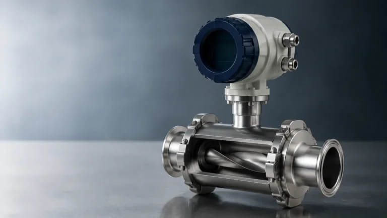
In the landscape of industrial process control, the accurate measurement of fluid movement is as critical as the monitoring of tank levels. A flow metter serves as the primary sensory organ for systems managing water treatment, chemical processing, and oil and gas distribution. While level measurement identifies the quantity of material in a stationary vessel, flow measurement quantifies the rate of transfer through pipes or open channels. Understanding the mechanical and electronic principles behind these instruments is essential for engineers and procurement specialists seeking to optimize plant efficiency and safety.
Selecting the correct flow metter requires a comprehensive analysis of the fluid’s physical properties, the installation environment, and the required precision. This guide provides a technical overview of flow measurement technologies, their relationship to level sensing, and practical considerations for industrial application.
Fundamental Principles of Flow Measurement
Before selecting a flow metter, it is necessary to understand the physics governing different measurement technologies. Most industrial flow instruments operate based on one of five primary physical principles: electromagnetic induction, ultrasonic wave propagation, vortex shedding, differential pressure, or level-to-flow conversion in open channels.
Electromagnetic Principle
Electromagnetic flow metters operate based on Faraday’s Law of Electromagnetic Induction. This law states that a conductor moving through a magnetic field produces an electrical signal proportional to the velocity of the conductor. In this application, the conductive liquid acts as the conductor. As the liquid flows through a magnetic field generated by the meter’s coils, electrodes detect a voltage. Since the cross-sectional area of the pipe is known, the meter calculates the volumetric flow rate based on the measured velocity.
Ultrasonic Principle
Ultrasonic technology is divided into two main methods: Transit-time and Doppler.
1. Transit-time: These instruments send ultrasonic pulses back and forth across the pipe. The pulse traveling with the flow moves faster than the pulse traveling against it. The time difference is directly proportional to the fluid velocity. This method is ideal for clean liquids.
2. Doppler: These meters reflect sound waves off particles or bubbles in the fluid. The frequency shift (Doppler effect) between the transmitted and received signal indicates the velocity. This is preferred for slurries or aerated liquids.
Vortex Shedding
Based on the Karman vortex street principle, a vortex flow metter places a "bluff body" (a non-streamlined object) in the flow path. As fluid passes this body, it creates alternating vortices. The frequency at which these vortices are shed is directly proportional to the velocity of the fluid. This technology is highly valued for its ability to measure steam, gases, and low-viscosity liquids.
Differential Pressure (DP)
DP flow metters utilize Bernoulli’s principle by introducing a restriction (such as an orifice plate or Venturi tube) in the pipe. This restriction creates a pressure drop. By measuring the pressure difference between the upstream and downstream sides, the system can calculate the flow rate, as the square root of the pressure drop is proportional to the flow velocity.
Open Channel Level-to-Flow
In many water treatment applications, flow is measured in open channels rather than closed pipes. Here, the relationship between level and flow is utilized. By installing a weir or flume of a specific geometry, the height (level) of the liquid correlates to a specific flow rate. High-precision ultrasonic or radar level sensors are used to measure this head height, which the controller then converts into a flow value using standardized formulas.
Technical Comparison and Selection Table
Choosing the right flow metter involves balancing performance requirements against fluid characteristics. The following table summarizes the primary technologies used in industrial automation.
| Technology | Suitable Fluids | Accuracy (Typical) | Key Advantages | Limitations |
| :— | :— | :— | :— | :— |
| Electromagnetic | Conductive liquids, slurries | ±0.5% of rate | No moving parts; zero pressure drop. | Requires minimum conductivity (>5 μS/cm). |
| Ultrasonic | Clean or dirty liquids | ±1.0% to ±2.0% | Non-invasive (clamp-on models available). | Sensitive to extreme turbulence or heavy aeration. |
| Vortex | Steam, gas, low-viscosity liquids | ±1.0% | Robust; no moving parts; high temp resistance. | Requires minimum Reynolds number to function. |
| Differential Pressure | Gas, liquid, steam | ±1.0% to ±3.0% | Well-standardized; low initial cost. | Creates pressure loss; requires regular maintenance. |
| Open Channel (Level-based) | Wastewater, irrigation water | ±2.0% to ±5.0% | Handles large volumes; easy to inspect. | Requires specific hydraulic structures (flumes). |
Installation Considerations and Best Practices
The performance of any flow metter is heavily dependent on its installation. Even the most advanced sensor will provide inaccurate data if the hydraulic conditions surrounding it are unstable.
Straight Pipe Requirements
Most flow metters require a "fully developed" flow profile to measure accurately. Turbulence caused by elbows, valves, or pumps can distort the velocity profile. Engineers typically follow the "10D/5D" rule: the meter should have a straight run of pipe equal to 10 times the pipe diameter upstream and 5 times the diameter downstream. If space is limited, flow conditioners or vanes may be necessary.
Pipe Orientation and Filling
For liquid applications, the pipe must remain completely full. If air pockets form at the top of the pipe, the flow metter will over-read or fail. Consequently, it is best to install meters in vertical pipes with upward flow or in the lowest section of a U-shaped horizontal pipe. For electromagnetic meters, the electrodes should be oriented horizontally to prevent them from being covered by sediment or insulated by air bubbles.
Grounding and Interference
Electromagnetic flow metters detect very small voltages (often in the millivolt range). To prevent electrical noise from interfering with the signal, the meter must be properly grounded to the fluid. In lined pipes or plastic piping, grounding rings are required to establish an electrical connection with the process liquid.
Limitations and Common Risks
While modern flow metter technology is highly reliable, certain conditions can lead to measurement failure or drift:
* Cavitation: If the pressure drops too low within the meter (especially in DP or Vortex meters), the liquid may vaporize, forming bubbles that damage the instrument and cause erratic readings.
* Scaling and Coating: In chemical or wastewater applications, material may build up on the internal walls or electrodes. This changes the cross-sectional area or insulates the sensors, leading to a gradual loss of accuracy.
* Viscosity Changes: Technologies like vortex and DP are sensitive to changes in fluid viscosity. If a process involves temperature fluctuations that significantly alter the fluid's thickness, the meter may require real-time compensation.
* Vibration: High levels of mechanical vibration in the piping system can interfere with the sensors in vortex and ultrasonic meters, introducing "noise" that the electronics may mistake for flow pulses.
To ensure long-term reliability, it is recommended to Review product options and application support to match the specific sensor material and technology to the chemical and physical demands of your process.

Integration with Level Measurement Systems
In many industrial environments, flow and level measurement are inseparable. For example, in a chemical dosing system, a flow metter monitors the rate of chemical injection while a hydrostatic level transmitter or a radar level meter monitors the remaining inventory in the bulk tank.
Welk provides a range of level measurement solutions that complement flow systems, including:
* Radar Level Meters: For non-contact measurement in volatile or corrosive tanks.
* Ultrasonic Level Sensors: Ideal for open channel flow calculations in flumes.
* Magnetic Level Gauges: For visual and electronic monitoring of high-pressure vessels.
By integrating these technologies, plant operators gain a holistic view of material movement, allowing for precise mass balance calculations and leak detection.
Frequently Asked Questions (FAQ)
Q: Can a flow metter measure both directions of flow?
A: Many electromagnetic and ultrasonic meters are inherently bi-directional and can track both forward and reverse flow. However, vortex and DP meters are typically uni-directional.
Q: How often should a flow metter be calibrated?
A: Calibration frequency depends on the criticality of the process and the fluid type. In regulated industries like food and pharma, annual calibration is common. For general water applications, a check every 2-3 years may suffice unless drift is detected.
Q: What is the difference between volumetric and mass flow?
A: Volumetric flow measures the space the fluid occupies (e.g., m³/h), while mass flow measures the actual weight of the fluid (e.g., kg/h). Mass flow is critical for gases and steam where density changes with temperature and pressure.
Q: Why is my ultrasonic flow metter showing a "signal lost" error?
A: This is often caused by excessive bubbles (aeration) or solids in the liquid, which scatter the ultrasonic signal. It can also occur if the pipe is not completely full or if the transducer couplant has dried out.
Final Project Confirmation Checklist
Before finalizing the procurement of a flow metter, project leads should confirm the following data points with their engineering team:
1. Fluid Conductivity: If selecting an electromagnetic meter, is the liquid conductivity above 5 μS/cm?
2. Pipe Material and Size: Is the pipe lined? What is the exact internal diameter (ID) for flow calculation?
3. Flow Range: What are the minimum and maximum expected flow rates (turn-down ratio)?
4. Process Conditions: What are the maximum operating pressure (bar) and temperature (°C)?
5. Output Requirements: Does the control system require 4-20mA, Modbus, HART, or pulse outputs?
By addressing these technical boundaries, you ensure that the selected flow metter provides the accuracy and longevity required for industrial automation. For comprehensive level and flow instrumentation needs, visiting the Main Page of a professional manufacturer like Welk can provide the necessary technical specifications and OEM/ODM customization options to meet specific project demands.