Flow Nozzle for Steam Flow Measurement
Flow Nozzle for Steam Flow Measurement
In industrial process engineering, steam remains the primary medium for heat transfer and power generation. Accurate measurement of steam flow is essential for boiler efficiency, energy balancing, and cost accounting. Among the various differential pressure (DP) flow elements, the flow nozzle for steam flow measurement stands out as a robust and reliable choice, particularly for high-velocity and high-pressure applications where standard orifice plates might fail due to erosion or mechanical stress.
This article provides a detailed engineering reference for the selection, principle of operation, and installation of flow nozzles in steam systems, aligning with the technical standards required for modern industrial automation.
Principles of Operation
The flow nozzle for steam flow measurement operates on the fundamental principle of differential pressure, governed by Bernoulli’s equation and the continuity equation. When steam flows through the constricted throat of a nozzle, its velocity increases, leading to a corresponding decrease in static pressure.
The Bernoulli Principle
As steam enters the elliptical inlet of the nozzle, the fluid is accelerated smoothly. The pressure difference ($ΔP$) between the upstream tap (high pressure) and the downstream tap (low pressure, usually located at the throat exit or further downstream depending on the design) is proportional to the square of the flow rate. The general flow equation is expressed as:
$$Q = C · E · A · √(2 · ΔP / ρ)$$
Where:
* Q is the mass flow rate.
* C is the discharge coefficient (accounting for viscous effects and turbulence).
* E is the velocity of approach factor.
* A is the cross-sectional area of the nozzle throat.
* ΔP is the measured differential pressure.
* ρ is the fluid density (highly dependent on steam pressure and temperature).
Discharge Coefficient (C)
One of the primary advantages of the flow nozzle is its high and stable discharge coefficient. Due to the curved inlet profile, the flow nozzle minimizes the "Vena Contracta" effect—the narrowing of the fluid stream after the constriction—which is prevalent in orifice plates. This results in a higher discharge coefficient (typically around 0.99 for high Reynolds numbers) and better pressure recovery.
Types of Flow Nozzles for Steam Applications
There are several standardized designs for flow nozzles, each governed by international standards such as ISO 5167 and ASME MFC-3M. Choosing the correct type depends on the pipe diameter, Reynolds number, and the specific steam conditions.
1. ISA 1932 Nozzle
The ISA 1932 nozzle features a rounded inlet and a cylindrical throat. It is widely used in Europe and international projects. Its design is suitable for a wide range of pipe sizes (50 mm to 500 mm) and is highly resistant to the abrasive nature of high-velocity steam.
2. ASME Long Radius Nozzle
Commonly used in North American power plants, this nozzle comes in two variations: the High-Beta Ratio (0.25 to 0.8) and the Low-Beta Ratio (0.2 to 0.5). The "long radius" refers to the elliptical shape of the inlet, which provides an exceptionally smooth transition for the steam, reducing turbulence and wear.
3. Venturi Nozzle
A hybrid between a standard nozzle and a Venturi tube, the Venturi nozzle combines the elliptical inlet of a nozzle with a divergent exit cone. This design offers the highest pressure recovery, making it ideal for systems where permanent pressure loss must be kept to an absolute minimum.
Why Use a Flow Nozzle for Steam Flow Measurement?
Steam applications present unique challenges, including high temperatures (often exceeding 500°C in superheated systems), high velocities, and the potential for water hammer. The flow nozzle is often preferred over other DP elements for several reasons:
1. Erosion Resistance: Steam, especially saturated steam, can carry droplets that cause "wire-drawing" or erosion on the sharp edges of orifice plates. The rounded profile of a flow nozzle is far more durable under these conditions.
2. High Velocity Handling: Steam lines often operate at high velocities to reduce pipe size and heat loss. Flow nozzles can handle higher flow rates and higher Reynolds numbers than orifice plates without significant degradation in accuracy.
3. Mechanical Strength: The rigid structure of the nozzle allows it to withstand the thermal expansion and mechanical shocks common in steam headers.
4. Stability: The discharge coefficient of a flow nozzle remains stable over a longer period compared to an orifice plate, which may lose its sharp edge over time, leading to measurement drift.
Technical Comparison and Selection Criteria
When evaluating a flow nozzle for steam flow measurement, engineers must compare it against other common technologies. The following table summarizes the key performance indicators.
| Feature | Flow Nozzle | Orifice Plate | Venturi Tube |
| :— | :— | :— | :— |
| Accuracy | Good (±1.0% to ±2.0%) | Fair (±2.0% to ±4.0%) | Excellent (±0.5% to ±1.0%) |
| Pressure Recovery | Moderate | Low | High |
| Erosion Resistance | High | Low | High |
| Installation Length | Moderate | Short | Long |
| Initial Cost | Moderate | Low | High |
| Suitability for Steam | Excellent | Fair (Saturated) | Good |
Material Selection
For steam service, material selection is critical. Common choices include:
* 304/316 Stainless Steel: Suitable for saturated steam and low-temperature superheated steam.
* Chrome-Moly Steels (e.g., F11, F22, P91): Required for high-temperature superheated steam in power generation to prevent creep and oxidation.
Installation and Engineering Guidelines
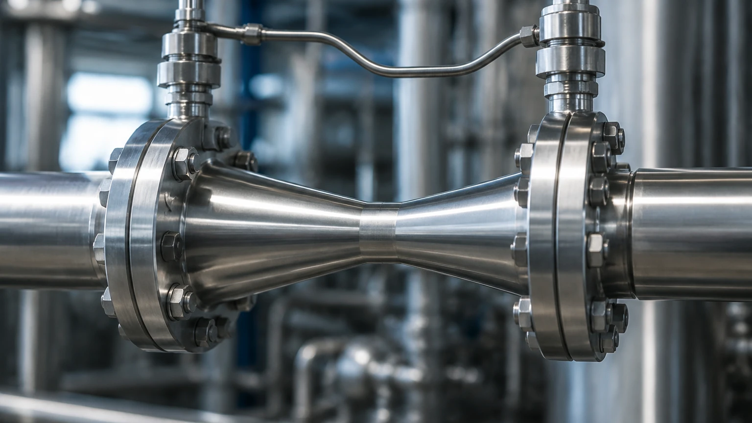
To ensure the accuracy of a flow nozzle for steam flow measurement, strict adherence to installation standards is required. Incorrect installation is the most common cause of measurement error in DP systems.
Straight Pipe Requirements
Flow nozzles require a fully developed flow profile. This typically necessitates a straight pipe run of 15 to 30 diameters upstream and 5 diameters downstream, depending on the presence of bends, valves, or reducers. If space is limited, flow conditioners may be required.
Impulse Line Configuration
In steam measurement, the impulse lines (the small-bore pipes connecting the nozzle taps to the DP transmitter) must be filled with water (condensate) to protect the transmitter from high temperatures.
* Condensate Pots: These are essential to maintain a constant liquid head in the impulse lines. They must be mounted at the same horizontal level to avoid a zero-shift error.
* Slope: Impulse lines should slope at least 1:12 towards the transmitter (for gas/steam) to allow air bubbles to vent back into the process line or to allow condensate to drain properly.
Orientation
* Horizontal Lines: Taps should be taken from the side of the pipe to prevent debris from entering the impulse lines (bottom taps) or air/non-condensable gases from entering (top taps).
* Vertical Lines: Flow nozzles can be installed in vertical lines, but the flow should ideally be in the upward direction to ensure the pipe remains full and to facilitate consistent condensate head in the impulse lines.
Limitations and Operational Maintenance
While the flow nozzle for steam flow measurement is highly durable, it is not without limitations:
1. Permanent Pressure Loss: Although better than orifice plates, flow nozzles still create a significant permanent pressure drop compared to Venturi tubes or ultrasonic meters.
2. Cost and Complexity: The manufacture of a flow nozzle requires precision machining of the elliptical profile, making it more expensive than a simple orifice plate. Installation often requires the nozzle to be welded between pipe sections or held between flanges, which can be labor-intensive.
3. Beta Ratio Limits: Nozzles are generally limited to beta ratios between 0.2 and 0.8. Outside this range, the uncertainty of the discharge coefficient increases significantly.
Maintenance
Routine maintenance should include checking the impulse lines for leaks and ensuring the condensate pots are properly leveled. During plant shutdowns, the internal bore of the nozzle should be inspected for scale buildup or significant pitting, especially in systems with poor water chemistry.
For engineers seeking comprehensive measurement solutions, including advanced level and flow instrumentation, reviewing the latest technical specifications on the Main Page can provide further insights into integrating these elements into a broader automation strategy.
Frequently Asked Questions (FAQs)
Q: Can a flow nozzle measure wet steam?
A: While a flow nozzle can physically handle wet steam better than an orifice plate, the presence of two phases (liquid and vapor) introduces significant measurement error. For accurate mass flow, the steam quality must be known, or the steam must be slightly superheated.
Q: How does the flow nozzle handle thermal expansion?
A: In high-temperature steam lines, the nozzle and the pipe will expand. The calculation of the flow rate must include an area thermal expansion factor ($F_a$) to account for the increase in the throat diameter at operating temperatures.
Q: Is a flow nozzle better than a Vortex flow meter for steam?
A: It depends on the application. Vortex meters offer a wider turndown ratio and lower pressure drop, but they have moving parts (the sensor diaphragm) and may not be as robust as a flow nozzle in high-pressure, high-velocity steam headers or where water hammer is a risk.
Conclusion
The flow nozzle for steam flow measurement remains a cornerstone of industrial flow metering. Its balance of durability, accuracy, and resistance to the harsh conditions of steam service makes it the preferred choice for critical process control and energy management. By understanding the underlying physical principles and following rigorous installation practices, plant operators can ensure reliable data for years of continuous service. For those looking to optimize their industrial measurement systems, exploring a wide range of sensors and transmitters is the next logical step in achieving operational excellence.