Flow Switch Sensor
Flow Switch Sensor
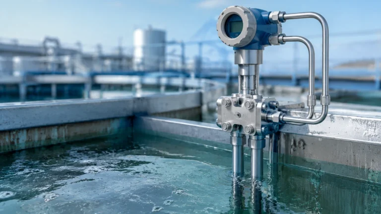
In the landscape of industrial process control, the flow switch sensor serves as a critical sentinel. Unlike flow meters that provide continuous measurement of fluid velocity or volume, a flow switch sensor is designed to monitor the presence or absence of flow, or to trigger an electrical signal when a specific flow rate threshold is reached. These devices are fundamental to protecting equipment from damage caused by dry running, ensuring the efficiency of cooling systems, and managing automated batching processes.
Selecting the right flow switch sensor requires a deep understanding of fluid dynamics, material compatibility, and the specific mechanical principles that govern different sensing technologies. This guide provides a technical overview of flow switch sensors, their operating principles, and the engineering criteria necessary for successful integration into industrial systems.
Measurement Principles of Flow Switch Sensors
Before selecting a device, it is essential to understand the physics behind the measurement. Flow switch sensors generally fall into two categories: mechanical and electronic (solid-state). Each relies on a different physical phenomenon to detect fluid movement.
Mechanical Principles (Paddle and Piston)
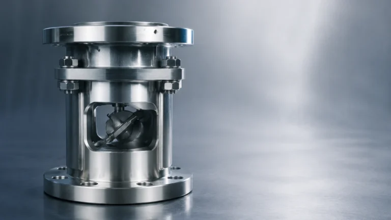
Mechanical flow switches utilize the kinetic energy of the moving fluid. In a paddle-style switch, a vane or paddle is suspended in the flow stream. As the fluid moves, it exerts force on the paddle, pushing it forward. This movement is transmitted through a mechanical linkage or a magnetic coupling to trigger a microswitch or a reed switch. Piston-type switches work similarly but use a spring-loaded piston that is displaced by the fluid pressure.
Thermal Dispersion Principle
Thermal dispersion sensors are solid-state devices with no moving parts. They typically consist of two temperature sensors (RTDs) immersed in the fluid. One sensor is heated, while the other serves as a reference for the process temperature. When the fluid is stationary, the temperature difference between the two sensors is at its maximum. As flow begins, the moving fluid carries heat away from the heated sensor, narrowing the temperature gap. The electronics translate this rate of heat loss into a flow signal. This method is highly sensitive and ideal for detecting low flow rates.
Ultrasonic Principle
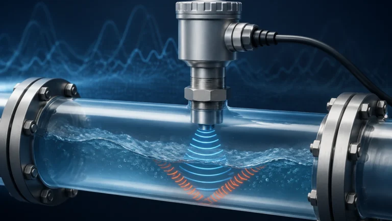
Ultrasonic flow switches use sound waves to detect movement. Doppler ultrasonic switches emit high-frequency sound into the liquid; if the liquid is moving, the sound reflects off bubbles or particles at a shifted frequency (the Doppler effect). If the frequency shift exceeds a set limit, the switch changes state. This non-invasive method is excellent for corrosive or high-pressure applications where penetrating the pipe wall is undesirable.
Magnetic/Inductive Principle
Based on Faraday’s Law of Induction, these sensors are used for conductive liquids. As a conductive fluid moves through a magnetic field generated by the sensor, a voltage is induced. If the induced voltage reaches a certain threshold, the flow switch sensor triggers. This technology is robust and offers no resistance to the flow path.
Key Evaluation Criteria for Selection
Choosing a flow switch sensor is not a one-size-fits-all process. Engineers must evaluate several variables to ensure long-term reliability and accuracy. For a broader look at how these sensors integrate with wider industrial measurement systems, you can visit our Main Page.
Media Properties
The chemical composition, viscosity, and cleanliness of the fluid are paramount.
- Viscosity: High-viscosity fluids can create significant drag on mechanical paddles, leading to false triggers or mechanical failure. Thermal sensors are also affected by changes in fluid thermal conductivity.
- Corrosivity: Ensure the wetted parts (316L stainless steel, Hastelloy, PVC, or PTFE) are compatible with the process media.
- Particulates: Mechanical switches can be prone to jamming if the fluid contains solids. In such cases, non-intrusive ultrasonic or thermal dispersion sensors are preferred.
Operating Environment
- Pressure and Temperature: Every sensor has a maximum pressure rating (e.g., 100 bar / 1450 psi) and temperature limit. Exceeding these can lead to seal failure or electronic malfunction.
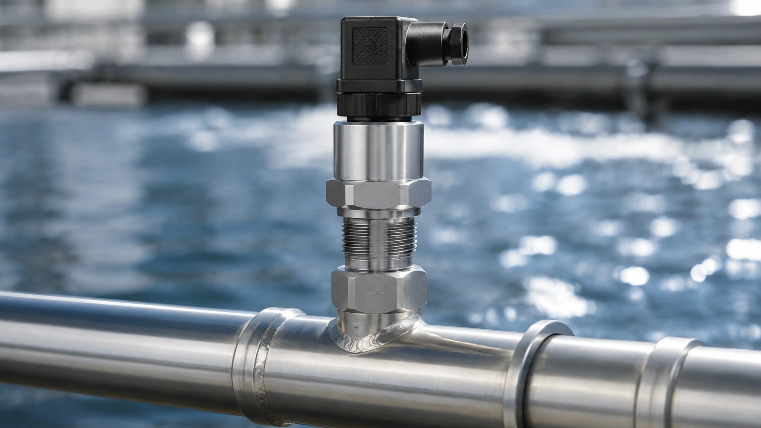
- Pipe Size: Some sensors are "insertion type," suitable for various pipe diameters via a T-piece or thread, while others are "in-line," specifically sized for a fixed pipe diameter (e.g., DN25 or 1").
Set Point and Hysteresis
The "set point" is the flow rate at which the switch changes state. Hysteresis (or differential) is the difference between the switch-on point and the switch-off point. Proper hysteresis prevents "chattering," where the switch rapidly flips back and forth when the flow is near the set point.
Practical Selection Table
| Technology | Best For | Advantages | Limitations |
| :— | :— | :— | :— |
| Paddle Switch | Water, general purpose | Low cost, simple operation | Moving parts wear out, pressure drop |
| Thermal Dispersion | Low flow, oils, gases | No moving parts, high sensitivity | Sensitive to fluid type changes |
| Piston Switch | High pressure, low flow | Accurate at low rates | Susceptible to clogging by solids |
| Ultrasonic | Corrosive/Dirty liquids | Non-invasive, no pressure drop | Requires particles or bubbles (Doppler) |
| Magnetic | Conductive liquids | No obstruction, long life | Only works with conductive media |
Installation Considerations
Correct installation is as important as selecting the right technology. Failure to follow engineering best practices can result in turbulent flow, which causes erratic switching.
1. Straight Pipe Runs: To ensure a stable flow profile, a flow switch sensor should typically be installed with at least 5 to 10 diameters of straight pipe upstream and 2 to 5 diameters downstream. This minimizes turbulence caused by valves, elbows, or pumps.
2. Orientation:
* Horizontal Pipes: Most sensors can be mounted on the top, side, or bottom, though side mounting is often preferred to avoid air pockets (top) or sediment buildup (bottom).
* Vertical Pipes: For liquid applications, flow should always be upward to ensure the pipe is completely full. Downward flow can lead to partially filled pipes, causing inaccurate readings.
3. Immersion Depth: For insertion-type sensors, the sensing element must be positioned correctly within the flow stream—usually in the center third of the pipe—to capture the most representative velocity.
4. Wiring and Protection: Use shielded cables to prevent electromagnetic interference (EMI) from nearby motors or variable frequency drives (VFDs). Ensure the housing meets the required NEMA or IP rating for the environment.
Common Risks and Limitations
Industrial environments present several challenges that can compromise the performance of a flow switch sensor:
* Scaling and Coating: In water treatment or chemical processing, minerals or polymers can build up on the sensor. In thermal dispersion switches, a coating acts as an insulator, significantly delaying response times. In mechanical switches, scaling can freeze the paddle in place.
* Cavitation: If a sensor is placed too close to a pump or a restrictive valve, cavitation (the formation of vapor bubbles) can occur. This creates erratic signals and can physically erode the sensor hardware.
* Flow Surges: Sudden spikes in flow can damage delicate mechanical paddles. If surges are expected, a more robust piston-style or a solid-state sensor should be used.
* Air Pockets: The presence of air in a liquid line is a common cause of false "no-flow" alarms. Ensuring the system is properly bled and the sensor is installed at a low point or in a vertical upward run can mitigate this.
Frequently Asked Questions (FAQ)
Q: Can a flow switch sensor be used to measure flow rate?
A: Generally, no. A flow switch is a binary device (On/Off). While some advanced thermal or ultrasonic models provide a secondary analog output (4-20mA), their primary purpose is to act as a switch based on a threshold.
Q: What is the difference between a normally open (NO) and normally closed (NC) contact?
A: A Normally Open switch remains open (no circuit) when there is no flow and closes when flow is detected. A Normally Closed switch is the opposite. The choice depends on your safety logic; for example, many pump protection circuits use NC contacts so that the circuit breaks (stopping the pump) if flow is lost or if power to the sensor fails.
Q: How often should a flow switch be calibrated?
A: For mechanical switches, an annual inspection for wear and debris is recommended. Electronic switches like thermal dispersion models are more stable but should be checked every 12 to 24 months depending on the criticality of the application and the tendency of the media to cause buildup.
Q: Can I use a water flow switch for oil?
A: It depends on the technology. A mechanical paddle switch may work if the viscosity is similar, but the set point will change due to the different density. A thermal dispersion switch calibrated for water will not work accurately for oil without recalibration, as the thermal conductivity of oil is significantly lower.
Conclusion
The flow switch sensor is an indispensable component in modern industrial automation, providing a reliable safety net for complex processes. By understanding the underlying measurement principles—whether mechanical, thermal, or ultrasonic—and carefully considering the installation environment and media properties, engineers can select a solution that ensures both safety and operational efficiency. Before finalizing a project design, always confirm the chemical compatibility of wetted materials and the electrical requirements of your control system to ensure a seamless integration. For more detailed technical specifications and product options, please refer to our Main Page.