Flow Transmitter Vortex
Flow Transmitter Vortex
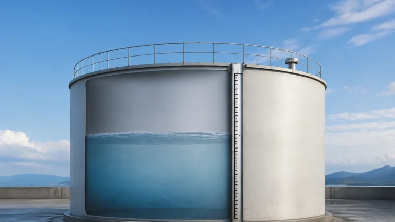
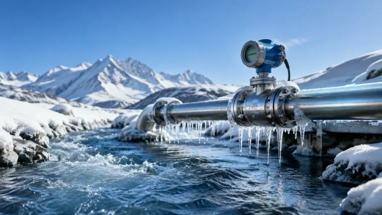
In the landscape of industrial process control, the accurate measurement of fluid movement is as critical as monitoring the contents of a storage vessel. While level measurement technologies—such as radar or ultrasonic sensors—provide data on volume and inventory, the flow transmitter vortex serves as a primary instrument for tracking the rate of media moving through a piping system. This technology is widely recognized for its versatility, lack of moving parts, and ability to handle extreme temperatures and pressures, making it a staple in steam, gas, and low-viscosity liquid applications.
Understanding the engineering principles, selection criteria, and installation requirements of a vortex flow transmitter is essential for process engineers aiming to optimize system efficiency and reduce maintenance overhead. This guide explores the technical foundations of vortex shedding and provides practical insights for integrating these instruments into industrial automation frameworks.
Measurement Principles: The Karman Vortex Street
The operation of a flow transmitter vortex is based on a physical phenomenon known as the Karman Vortex Street. This principle describes the behavior of a fluid as it encounters a non-streamlined object, often referred to as a bluff body or a shedder bar, placed directly in the flow path.
The Physics of Shedding
As the fluid (liquid, gas, or steam) flows past the bluff body, it cannot follow the sharp contours of the object. This causes the fluid layers to separate and roll up into alternating vortices (swirls) on either side of the body. These vortices are shed downstream in a predictable, alternating pattern.
The frequency at which these vortices are shed is directly proportional to the velocity of the fluid. This relationship is defined by the Strouhal equation:
f = (St × V) / d
Where:
* f is the vortex shedding frequency (Hz).
* St is the Strouhal number (a dimensionless constant specific to the shape of the bluff body).
* V is the velocity of the fluid (m/s).
* d is the width of the bluff body (m).
Because the Strouhal number remains constant over a wide range of Reynolds numbers, the frequency of shedding provides a highly linear representation of the flow velocity. A piezoelectric sensor, typically located behind or within the bluff body, detects the pressure fluctuations caused by each vortex and converts them into an electrical signal. The transmitter electronics then process this frequency into a standardized output, such as 4-20mA, pulse, or digital protocols like HART or Modbus.
Key Components and Construction
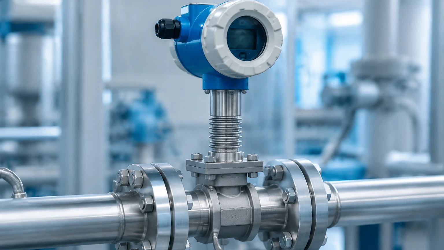
A standard flow transmitter vortex consists of three primary elements designed to withstand harsh industrial environments:
1. The Meter Body: Usually constructed from robust materials like 304 or 316 stainless steel, the body houses the bluff body and provides the connection points (flanged, wafer, or threaded) for the piping system.
2. The Sensor: Most modern vortex meters use piezoelectric crystals. These sensors are isolated from the process media to prevent corrosion and mechanical wear, ensuring long-term stability.
3. The Transmitter Electronics: This unit performs signal conditioning, noise filtering (to eliminate pipe vibration interference), and temperature/pressure compensation if the meter is a multivariable model.
Selection Criteria for Vortex Flow Transmitters
Choosing the correct instrument requires a thorough analysis of the process conditions. Unlike level measurement, where the dielectric constant or surface turbulence are primary concerns, vortex flow measurement is heavily dependent on fluid dynamics and Reynolds numbers.
Fluid Type and Phase
Vortex meters are exceptionally effective for:
* Steam: Both saturated and superheated steam.
* Gases: Compressed air, nitrogen, carbon dioxide, and natural gas.
* Liquids: Water, chemicals, and light hydrocarbons with low viscosity.
Selection Table: Application Suitability
| Parameter | Requirement/Limit | Engineering Note |
| :— | :— | :— |
| Reynolds Number | > 20,000 | Below this, the shedding becomes non-linear. |
| Viscosity | < 10-15 cP | High viscosity dampens vortex formation. |
| Temperature Range | -40°C to +350°C | High-temp versions require remote electronics. |
| Pressure Rating | Up to PN100 (10 MPa) | Depends on flange rating and body material. |
| Turndown Ratio | 10:1 to 30:1 | Higher for gas/steam than for liquids. |
| Accuracy | ±0.75% to ±1.5% | Typically higher for liquids than for gases. |
Multivariable Capabilities
For steam and gas applications, mass flow is often more important than volumetric flow. Advanced vortex transmitters include integrated temperature and pressure sensors. This allows the device to calculate real-time density and provide a compensated mass flow output, eliminating the need for separate external sensors and flow computers. For comprehensive process monitoring, engineers often pair these flow systems with reliable Main Page solutions to ensure both inflow/outflow and vessel inventory are accurately tracked.
Installation Considerations
The performance of a flow transmitter vortex is highly sensitive to the flow profile. A fully developed, symmetrical flow profile is required for accurate vortex shedding.
Straight Pipe Requirements
To ensure accuracy, the meter must be installed with sufficient straight piping both upstream and downstream. Obstructions like elbows, valves, and reducers create turbulence that interferes with vortex formation.
* Upstream: Minimum 10D to 40D (where D is the pipe diameter), depending on the type of upstream obstruction.
* Downstream: Minimum 5D.
If the required straight runs cannot be met, flow straighteners or vanes may be necessary to condition the fluid before it reaches the bluff body.
Orientation and Piping
* Horizontal Piping: The most common installation. For liquid applications, the pipe must remain full. For steam, the meter should be oriented to prevent condensate from pooling around the sensor.
* Vertical Piping: Acceptable for both upward and downward flow, provided the pipe remains full (for liquids). Upward flow is generally preferred for liquid applications to ensure the meter body is always flooded.
* Vibration: While modern transmitters include digital signal processing (DSP) to filter out noise, excessive pipe vibration can still cause false readings. Supporting the pipe near the meter is a recommended practice.
Limitations and Practical Constraints
While the flow transmitter vortex is a robust tool, it is not a "one-size-fits-all" solution. Understanding its limitations prevents costly misapplications.
1. Low Flow Cutoff: Because vortex shedding relies on fluid velocity, there is a minimum flow rate below which vortices are too weak to be detected. This is known as the "low flow cutoff." If the process frequently operates at very low velocities, a vortex meter may not be suitable.
2. Viscosity Sensitivity: High-viscosity fluids (such as heavy oils) dampen the formation of vortices. Generally, if the viscosity exceeds 15 centipoise (cP), the accuracy of the meter degrades significantly.
3. Cavitation: In liquid applications, if the pressure drops too low at the bluff body, the liquid may vaporize (cavitate), causing sensor damage and measurement errors. Maintaining a backpressure of at least 2.0 times the pressure drop plus 1.3 times the vapor pressure is a standard safety margin.
4. Abrasive Media: While there are no moving parts, highly abrasive slurries can wear down the sharp edges of the bluff body over time. This changes the Strouhal number and leads to measurement drift.
Maintenance and Troubleshooting
One of the primary advantages of the vortex technology is the minimal maintenance required. Since there are no bearings to wear out or rotors to clog, routine service is usually limited to visual inspections and periodic calibration verification.
Common Troubleshooting Steps
* No Signal Output: Check power supply and wiring. Ensure the flow rate is above the minimum Reynolds number threshold.
* Inaccurate Readings: Verify that the internal pipe diameter matches the meter's configuration. Inspect the bluff body for buildup or erosion. Ensure the straight pipe run requirements are met.
* Unstable Signal: This is often caused by pipe vibration or electrical interference. Check the grounding of the transmitter and ensure the DSP settings are optimized for the application.
Frequently Asked Questions (FAQ)
Q: Can a vortex flow transmitter measure saturated steam?
A: Yes, it is one of the most common applications for this technology. However, it is recommended to use a multivariable version with temperature compensation to account for changes in steam density.
Q: How does a vortex meter compare to an ultrasonic flow meter?
A: Vortex meters are generally more cost-effective for high-temperature steam and gas applications. Ultrasonic meters (especially clamp-on types) are preferred when the process cannot be interrupted for installation or when measuring non-conductive liquids in very large pipes.
Q: Is the bluff body prone to clogging?
A: The bluff body is designed to be a "shedder," not a filter. While it can catch large debris, normal particulate matter in gases and liquids typically passes through. However, for fluids that tend to coat surfaces (like wax or heavy resins), periodic cleaning may be required.
Q: What is the typical lifespan of a vortex sensor?
A: Because the piezoelectric sensor is usually isolated from the process, it can last for 10 to 20 years in non-corrosive environments. The primary factor in lifespan is the compatibility of the meter body material with the process fluid.
Conclusion
The flow transmitter vortex remains a cornerstone of industrial flow measurement due to its reliability and lack of mechanical wear. By adhering to strict installation guidelines and accurately matching the meter to the fluid properties, engineers can achieve precise control over their processes. Whether managing steam distribution in a power plant or monitoring nitrogen flow in a chemical facility, the vortex meter provides the data necessary for operational excellence. For those seeking to integrate flow data with comprehensive tank and vessel monitoring, exploring advanced Main Page options ensures a holistic approach to industrial automation and resource management.