Field Instruments
Field Instruments
In the landscape of industrial automation, field instruments serve as the primary interface between physical processes and control systems. These devices are responsible for sensing, measuring, and transmitting real-time data regarding process variables such as level, pressure, flow, and temperature. In level measurement specifically, field instruments must provide high accuracy and reliability to ensure operational safety, inventory management, and process efficiency. For engineers and procurement specialists, selecting the appropriate technology requires a deep understanding of measurement principles, environmental constraints, and the specific characteristics of the medium being measured.
Core Measurement Principles of Level Field Instruments
Before selecting a device, it is essential to understand the physics behind how these field instruments interact with the process medium. Level measurement technologies are generally categorized into non-contact and contact methods.
Radar Level Measurement (Time-of-Flight)
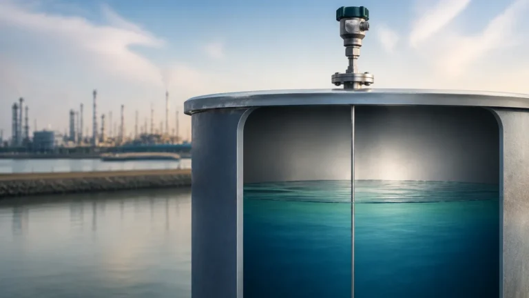
Radar level meters utilize high-frequency electromagnetic waves, typically in the 26 GHz or 80 GHz range. The instrument emits a pulse toward the material surface, which reflects a portion of the energy back to the sensor. The device measures the time it takes for the signal to travel to the surface and back (Time-of-Flight). Since electromagnetic waves travel at the speed of light, the distance is calculated using the formula:
Distance = (Speed of Light × Travel Time) / 2
Radar instruments are highly versatile because electromagnetic waves are largely unaffected by temperature fluctuations, vacuum, or high pressure.
Ultrasonic Level Measurement
Similar to radar, ultrasonic sensors use the Time-of-Flight principle but employ sound waves instead of electromagnetic pulses. The sensor emits an ultrasonic pulse (typically 20 kHz to 70 kHz) that reflects off the liquid or solid surface. Because the speed of sound is influenced by air temperature, these instruments usually include an integrated temperature sensor to compensate for velocity changes. However, they cannot function in a vacuum, as sound requires a medium to travel.
Hydrostatic Level Measurement
Hydrostatic transmitters measure the pressure exerted by a liquid column at a specific depth. This principle relies on the relationship between pressure, density, and height:
P = ρ × g × h
Where *P* is pressure, *ρ* (rho) is the density of the liquid, *g* is the gravitational constant, and *h* is the height of the liquid. As long as the density of the medium remains constant, the pressure measured at the bottom of the tank is directly proportional to the level.
Magnetic Level Gauges (Buoyancy Principle)
Magnetic level gauges utilize Archimedes' principle of buoyancy. A float containing a permanent magnet assembly is placed inside a bypass chamber connected to the vessel. As the liquid level rises or falls, the float moves accordingly. This movement acts upon a series of magnetic flaps or a sensing rod outside the chamber, providing a visual or electronic indication of the level without the electronics coming into direct contact with the process medium.
Technical Selection Criteria for Field Instruments
Choosing the correct field instruments involves evaluating the chemical and physical properties of the application. Engineers must confirm the following parameters before procurement:
1. Medium Characteristics: Is the medium a liquid, slurry, or solid? What is its dielectric constant (for radar) or density (for hydrostatic)? Corrosive media may require specialized wetted materials like PTFE or Hastelloy.
2. Process Conditions: Operating temperatures can range from cryogenic levels to over 400°C. Similarly, pressures may vary from full vacuum to over 100 bar (10 MPa). Field instruments must be rated for these extremes.
3. Vessel Geometry: The height of the tank, the presence of internal obstructions (like agitators or heating coils), and the shape of the tank bottom (conical vs. flat) influence sensor placement and technology choice.
4. Accuracy and Output Requirements: Standard industrial applications may require ±3 mm to ±10 mm accuracy, while custody transfer applications demand sub-millimeter precision. Common outputs include 4-20mA HART, RS485 Modbus, or Foundation Fieldbus.
For a comprehensive overview of available technologies and detailed technical specifications, professionals can consult the Main Page for specific product data sheets.
Comparative Selection Table
The following table provides a general comparison of common field instruments used in level measurement applications.
| Technology | Contact Type | Ideal Media | Max Range (Typical) | Key Advantage | Major Limitation |
| :— | :— | :— | :— | :— | :— |
| 80GHz Radar | Non-contact | Liquids, Solids, Corrosives | 30m – 120m | High precision, small beam angle | Higher initial cost |
| Ultrasonic | Non-contact | Water, Wastewater | 15m – 20m | Cost-effective for liquids | Affected by foam and vacuum |
| Hydrostatic | Contact | Clean liquids, Oils | 200m (Submersible) | Simple installation | Requires constant density |
| Magnetic Gauge| Contact | Chemicals, Boilers | 6m (Standard) | Visual local indication | Moving parts may wear |
| Level Switch | Contact | High/Low Alarms | N/A | Point level detection | No continuous measurement |
Installation and Engineering Best Practices
Even the most advanced field instruments will fail to provide accurate data if installed incorrectly. Proper engineering during the installation phase is critical for long-term reliability.
Mounting Position
For non-contact sensors (Radar and Ultrasonic), the device should be mounted at least 200mm to 500mm away from the tank wall to avoid signal interference from wall reflections. It should also be positioned away from the center of the tank if a vortex is likely to form during agitation, as the slanted surface of a vortex can deflect signals away from the sensor.
Nozzle Design
The mounting nozzle should be as short and wide as possible. If a nozzle is too long or narrow, it can create "ringing" or internal reflections that interfere with the sensor's ability to detect the actual material surface. This is particularly important for ultrasonic sensors which have a "dead zone" (blocking distance) directly beneath the transducer where measurements cannot be taken.
Avoiding Obstructions
Field instruments should be installed in a location where the signal beam does not intersect with internal structures such as ladders, pipes, or agitator blades. If obstructions are unavoidable, many modern radar instruments offer "False Echo Suppression" software, allowing the user to map out and ignore static reflections from internal tank hardware.

Operational Limitations and Environmental Factors
While field instruments are designed for rugged environments, certain conditions can impact their performance:
* Foam and Turbulence: Heavy foam on a liquid surface can absorb ultrasonic and radar signals, leading to signal loss. In such cases, a stilling well or a bypass pipe may be required to provide a calm surface for measurement.
* Dust and Vapor: Dense dust in silos can attenuate high-frequency signals. Similarly, heavy steam or vapor can change the speed of sound, affecting ultrasonic accuracy. Radar is generally the preferred choice for high-vapor environments.
* Dielectric Constant (εr): Radar measurement depends on the reflectivity of the medium. Materials with a low dielectric constant (like certain oils or liquefied gases) reflect less energy. If the εr is below 1.4, a guided wave radar or a high-sensitivity 80GHz radar is often necessary.
Frequently Asked Questions (FAQs)
Q: Can ultrasonic field instruments be used in pressurized tanks?
A: Generally, no. Ultrasonic sensors rely on the speed of sound through air or gas. Changes in pressure alter the density of the gas, which significantly changes the speed of sound and introduces large measurement errors. Radar is the standard for pressurized vessels.
Q: What is the difference between a level transmitter and a level switch?
A: A level transmitter provides continuous measurement (e.g., 0% to 100% full), whereas a level switch provides point level detection (e.g., "tank is full" or "tank is empty") to trigger an alarm or stop a pump.
Q: Why is 80GHz radar becoming the industry standard over 26GHz?
A: 80GHz radar has a much smaller beam angle (often as narrow as 3 degrees), which allows it to avoid internal obstructions more easily and provides better performance in narrow or tall vessels.
Q: How often do hydrostatic level sensors need calibration?
A: Calibration frequency depends on the stability of the medium's density and the drift specifications of the sensor. In most water treatment applications, an annual check is sufficient, but in chemical processes where density varies with temperature, more frequent recalibration or temperature compensation is required.
Summary of Field Instrument Selection
Successful implementation of field instruments requires a balance between technical capability and cost-efficiency. While radar offers the highest versatility, hydrostatic and ultrasonic sensors remain valuable for simpler, more budget-conscious applications. By confirming the medium properties, vessel constraints, and environmental factors beforehand, engineers can ensure the selected instrumentation provides the reliable data necessary for modern industrial control. For further technical guidance and product selection, visiting the Main Page provides access to professional-grade measurement solutions tailored for diverse industrial sectors.