Flow Ultrasonic
Flow Ultrasonic
In modern industrial process control, the ability to measure fluid movement without obstructing the flow path has become a critical requirement. Flow ultrasonic technology represents a sophisticated category of non-invasive measurement solutions that utilize acoustic waves to determine the velocity and volume of liquids. Whether applied in open-channel wastewater systems or high-pressure chemical pipelines, these instruments offer a combination of accuracy and low maintenance that traditional mechanical meters often struggle to match.
For engineering professionals, understanding the distinction between different ultrasonic methodologies—and how they integrate with level measurement—is essential for optimizing plant efficiency. This guide explores the principles, applications, and selection criteria for flow ultrasonic systems in industrial environments.
Principles of Ultrasonic Measurement
Ultrasonic measurement relies on the propagation of high-frequency sound waves (typically above 20 kHz) through a medium. In the context of flow, there are two primary methods used: the transit-time method and the Doppler effect. Additionally, in many B2B applications such as water treatment, flow is calculated indirectly through level measurement in open channels.
Transit-Time Method
This method is designed for clean liquids. It utilizes two transducers that act as both transmitters and receivers. They are mounted on opposite sides of a pipe. One pulse is sent upstream and another downstream. Because the moving fluid carries the sound waves, the pulse traveling downstream reaches the receiver faster than the pulse traveling upstream. The difference in time (the transit time) is directly proportional to the velocity of the fluid.
Doppler Effect Method
Doppler flow meters are used for liquids containing suspended solids or aerated bubbles. The sensor emits an ultrasonic signal that reflects off these particles. Because the particles are moving with the fluid, the frequency of the reflected signal is shifted (the Doppler shift). By measuring this frequency change, the instrument calculates the flow velocity.
Level-to-Flow Conversion (Open Channels)
In many industrial automation and water treatment scenarios, flow ultrasonic technology refers to an ultrasonic level sensor mounted above a primary device, such as a weir or a flume. The sensor measures the height (head) of the liquid. Since the geometry of the weir or flume is known, the flow rate can be calculated using standardized mathematical formulas. This is a non-contact method that avoids the wear and tear associated with submerged sensors.
Open Channel Flow Ultrasonic Applications
Open channel flow measurement is prevalent in irrigation, sewage treatment, and industrial discharge monitoring. Because the fluid is not under pressure and often contains debris, non-contact ultrasonic sensors are the preferred choice.
Primary Devices: Weirs and Flumes
To measure flow in an open channel, a primary device must be installed to create a predictable relationship between the liquid level and the flow rate.
1. Weirs: These are obstructions (like a wall) built across an open channel. Common types include V-notch, rectangular, and Cipolletti weirs. The level of the liquid behind the weir is measured by the ultrasonic sensor.
2. Flumes: These are specially shaped channel sections (like the Parshall flume) that restrict the flow and then expand it. Flumes are often preferred over weirs because they are self-cleaning and cause less head loss.
The Role of the Ultrasonic Sensor
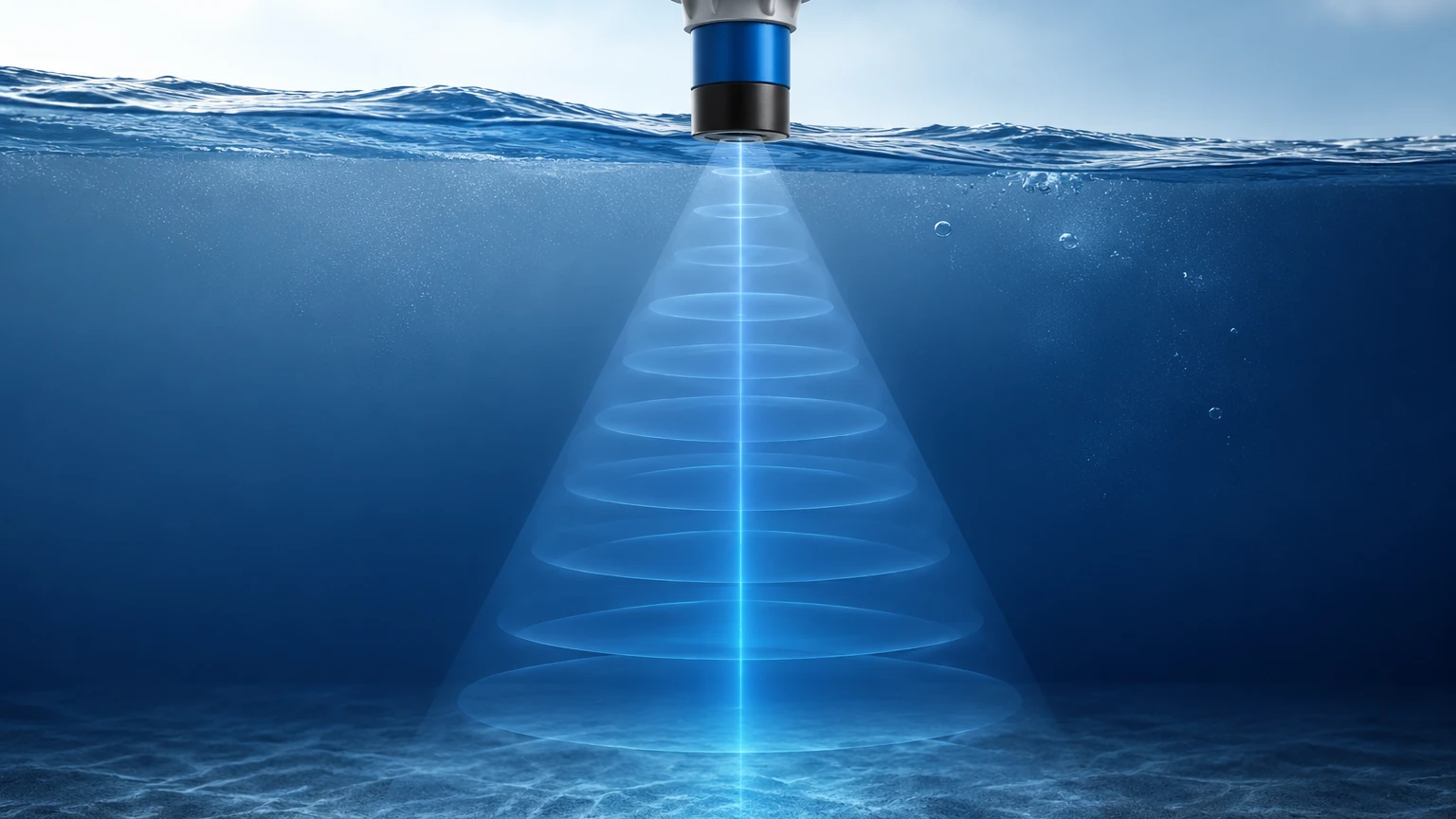
The ultrasonic sensor is mounted at a specific distance upstream from the weir or flume. It emits a pulse that reflects off the liquid surface. The time taken for the echo to return allows the transmitter to calculate the exact level. Advanced transmitters then convert this level into a flow rate (e.g., m³/h or liters/second) based on the programmed dimensions of the primary device.
Technical Selection Criteria
Selecting the right flow ultrasonic system requires an analysis of the fluid, the environment, and the existing infrastructure. The following table provides a comparison of the different ultrasonic approaches.
| Feature | Transit-Time (Inline) | Doppler (Inline) | Ultrasonic Level (Open Channel) |
| :— | :— | :— | :— |
| Fluid Type | Clean liquids, low solids | Dirty liquids, aerated | Any liquid in open channels |
| Installation | Inline or Clamp-on | Inline or Clamp-on | Above the liquid (Non-contact) |
| Accuracy | High (±0.5% to 1%) | Moderate (±2% to 5%) | High (Depends on primary device) |
| Maintenance | Low | Low | Very Low |
| Primary Use | Oil, chemicals, pure water | Slurries, wastewater | Effluent, irrigation, flumes |
Key Considerations for Engineers
* Fluid Properties: Does the liquid contain bubbles? If so, a transit-time meter will fail, and a Doppler meter or an open-channel level-to-flow system should be used.
* Pipe/Channel Material: For inline systems, the material must allow sound waves to pass through. For open channels, the surface of the liquid must be relatively calm to ensure a reliable echo.
* Power Supply: In remote water treatment sites, low-power or loop-powered (24V DC) sensors are often required to integrate with existing PLC systems.
Installation and Engineering Best Practices
Proper installation is the single most important factor in the accuracy of a flow ultrasonic system. Even the most advanced sensor will provide inaccurate data if the physics of the installation are ignored.
Blocking Distance (Dead Zone)
Every ultrasonic sensor has a "blocking distance" or "dead zone" directly beneath the transducer face, typically ranging from 0.20m to 0.50m. The sensor cannot measure any level within this zone. Therefore, the sensor must be mounted high enough so that even at maximum flow (highest liquid level), the liquid does not enter the dead zone.
Mounting and Alignment
For open channel flow, the sensor must be mounted perfectly perpendicular to the liquid surface. If the sensor is tilted, the ultrasonic pulse will reflect away from the transducer, resulting in a "lost echo" signal. In outdoor installations, a sunshade should be used to prevent the sensor housing from overheating, which can affect the internal temperature compensation circuitry.
Temperature Compensation
The speed of sound in air changes by approximately 0.17% per degree Celsius. In outdoor applications where temperatures can fluctuate from -20°C to +60°C, integrated temperature sensors are mandatory. These sensors allow the flow ultrasonic transmitter to adjust its calculations in real-time based on the ambient air temperature.
Stilling Wells
In applications where the liquid surface is turbulent or covered in foam, a stilling well (a vertical pipe submerged in the flow) can be used. The ultrasonic sensor measures the level inside the pipe, where the surface is calm. However, the pipe must be vented to ensure the level inside matches the level outside, and it must be kept free of debris.
Challenges and Limitations
While flow ultrasonic technology is highly versatile, it is not a universal solution. Engineers must be aware of the following limitations:
1. Surface Foam: Heavy foam can absorb the ultrasonic signal rather than reflecting it. In these cases, a radar level meter or a hydrostatic pressure transmitter may be a better choice for flow calculation.
2. Vapor and Steam: High concentrations of heavy vapors or steam can change the composition of the air through which the sound wave travels, leading to measurement errors.
3. Wind and Turbulence: Strong winds in open-air installations can "blow" the ultrasonic pulse away, while extreme turbulence can create an unstable surface that scatters the echo.
4. Acoustic Noise: High-frequency noise from nearby machinery or pneumatic valves can occasionally interfere with the sensor's frequency, although most modern digital sensors use filtering algorithms to mitigate this.
Practical Maintenance and Troubleshooting
One of the primary benefits of ultrasonic systems is the lack of moving parts. However, periodic checks are still necessary to ensure long-term reliability.
* Transducer Cleaning: In humid or dusty environments, condensation or buildup can occur on the transducer face. A simple wipe with a soft cloth is usually sufficient to restore performance.
* Calibration Verification: For compliance with environmental regulations, the flow rate should be verified annually. This often involves measuring the level manually with a calibrated rule and comparing it to the transmitter's reading.
* Signal Strength Monitoring: Most modern transmitters provide a "signal quality" or "echo strength" value. A gradual decline in this value may indicate that the sensor is becoming dirty or that the primary device (weir/flume) is becoming clogged.
Frequently Asked Questions (FAQ)
Q: Can ultrasonic flow meters measure gas flow?
A: While specialized ultrasonic meters exist for high-pressure gas pipelines, the standard industrial ultrasonic sensors used for level and open-channel flow are designed for liquids.
Q: How far can the transmitter be from the sensor?
A: In split-type systems, the cable between the ultrasonic transducer and the remote transmitter can typically be up to 50 or 100 meters, depending on the manufacturer’s specifications and the use of shielded cabling to prevent EMI.
Q: Is ultrasonic better than radar for flow measurement?
A: It depends on the environment. Ultrasonic is generally more cost-effective for standard water and wastewater applications. Radar is superior in applications with heavy steam, dust, or fluctuating gas compositions above the liquid.
Q: What is the minimum flow rate an ultrasonic meter can detect?
A: For open channels, the minimum flow is determined by the primary device (the weir or flume). The ultrasonic sensor can typically measure levels as low as 20mm to 50mm with high accuracy.
Conclusion and Next Steps
Flow ultrasonic technology provides a reliable, non-invasive, and cost-effective method for monitoring fluid movement across a wide range of industrial sectors. By understanding the physical principles of sound propagation and the specific requirements of primary devices like flumes and weirs, engineers can implement systems that offer years of maintenance-free service.
When specifying equipment for a project, it is vital to consult with manufacturers who offer a broad range of technologies, as the ideal solution may involve a combination of ultrasonic, radar, or hydrostatic sensors depending on the specific process conditions. For those looking to compare specific instrument specifications or explore customized OEM solutions, visiting the Main Page of a dedicated manufacturer like Welk is a recommended next step to ensure the selected hardware meets the technical demands of the application.