Ultrasonic Gas Meters
Ultrasonic Gas Meters
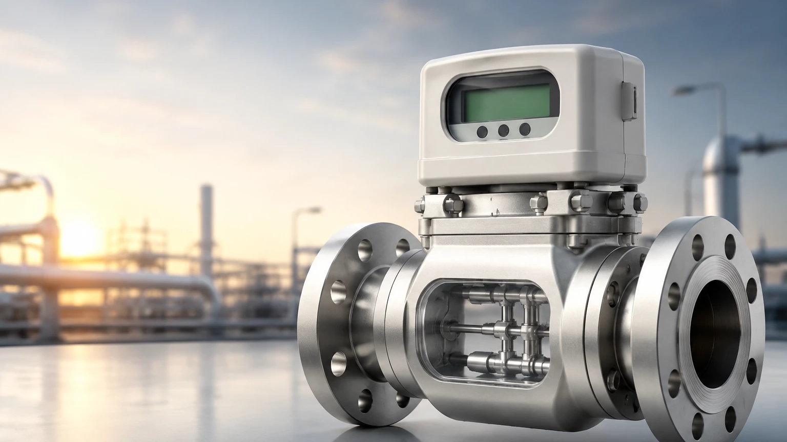
In the landscape of industrial process control and custody transfer, the accurate measurement of gas flow is a fundamental requirement. Among the various technologies available, ultrasonic gas meters have emerged as a preferred solution for high-precision applications. Unlike traditional mechanical meters that rely on moving parts, ultrasonic technology utilizes acoustic signals to determine flow velocity, offering significant advantages in terms of reliability, rangeability, and maintenance. This guide provides a detailed technical overview of ultrasonic gas meters, their operating principles, selection criteria, and practical installation considerations for engineering professionals.
Measurement Principles of Ultrasonic Gas Meters
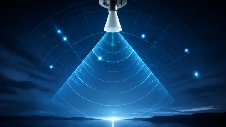
Ultrasonic gas meters primarily operate based on the transit-time differential principle. This method relies on the fact that sound waves traveling in the direction of a flowing medium move faster than sound waves traveling against the flow. By measuring the time difference between these two signals, the meter can calculate the velocity of the gas with high precision.
The Transit-Time Method
The device contains pairs of ultrasonic transducers, usually piezoelectric crystals, mounted on opposite sides of the pipe. One transducer acts as a transmitter while the other acts as a receiver. The process involves two distinct phases:
1. Downstream Transmission: A pulse is sent from the upstream transducer to the downstream transducer.
2. Upstream Transmission: A pulse is sent from the downstream transducer back to the upstream transducer.
If the gas is stationary, the transit time in both directions is identical. However, when the gas is moving, the pulse traveling downstream is accelerated by the flow, while the pulse traveling upstream is decelerated. The time difference ($\Delta t$) is directly proportional to the average flow velocity along the acoustic path. When combined with the cross-sectional area of the pipe and the known geometry of the meter, the volumetric flow rate can be calculated.
Multi-Path Configurations
Industrial-grade ultrasonic gas meters often employ multiple acoustic paths (chords) to account for non-ideal flow profiles. In a single-path meter, a distorted flow profile—caused by upstream elbows or valves—can lead to significant measurement errors. Multi-path meters (ranging from 2 to 18 paths) sample the velocity at different points across the pipe cross-section. Advanced algorithms then integrate these readings to provide a weighted average that is highly resistant to swirl and turbulence.
Key Evaluation Criteria for Industrial Applications
Selecting the appropriate ultrasonic gas meter requires a thorough understanding of the process conditions and the specific requirements of the application. The following criteria are essential for technical evaluation:
Accuracy and Repeatability
For custody transfer applications, where gas is bought and sold, high accuracy is paramount. High-end ultrasonic meters can achieve accuracies of better than ±0.1% to ±0.5% after flow calibration. For process monitoring where extreme precision is less critical, accuracies of ±1.0% to ±2.0% may be acceptable. Repeatability is typically within the range of 0.05% to 0.1%.
Pressure and Temperature Ratings
Gas density and the speed of sound are heavily influenced by temperature and pressure. It is vital to ensure the meter body and transducers are rated for the maximum operating pressure (often up to 100 bar or higher in transmission pipelines) and the temperature range of the process (typically -40°C to +150°C). High-pressure environments actually improve the coupling of ultrasonic signals between the transducer and the gas, whereas very low pressures (near atmospheric) can make signal transmission more challenging.
Turndown Ratio
One of the greatest strengths of ultrasonic gas meters is their wide turndown ratio, often exceeding 100:1. This allows a single meter to accurately measure both the very low flows during off-peak periods and the high flows during peak demand. This capability often eliminates the need for parallel meter runs of different sizes.
Material Compatibility
The meter body is typically constructed from carbon steel, stainless steel, or specialized alloys for corrosive gases. The transducers must also be compatible with the gas composition, particularly if H2S (sour gas) or moisture is present.
Selection Reference Table
The following table outlines typical specifications for different categories of ultrasonic gas measurement applications:
| Feature | Custody Transfer | Industrial Process Control | Flare Gas Measurement |
| :— | :— | :— | :— |
| Typical Accuracy | ±0.1% to ±0.5% | ±1.0% to ±2.0% | ±2.0% to ±5.0% |
| Path Configuration | Multi-path (4-18 paths) | Single or Dual path | Single or Dual path |
| Flow Velocity Range | 0.3 to 30 m/s | 0.5 to 40 m/s | 0.03 to 100+ m/s |
| Pressure Drop | Negligible | Negligible | Negligible |
| Diagnostics | Advanced (SoS, SNR) | Standard | Standard |
| Calibration | High-pressure flow lab | Factory air/water | Field verification |
Installation Considerations and Best Practices
While ultrasonic gas meters have no moving parts and are less sensitive to installation effects than turbine or orifice meters, certain engineering standards must be followed to ensure performance.
Straight Pipe Requirements
To ensure a fully developed and stable flow profile, ultrasonic meters require a minimum length of straight pipe upstream and downstream. A common guideline is 10D (ten diameters) upstream and 3D downstream. If space is limited, high-performance flow conditioners (such as perforated plates or tube bundles) can be installed upstream to reduce the required straight run to as little as 5D.
Orientation and Mounting
For gases that may contain liquids (wet gas), the transducers should be mounted in a horizontal plane (3 o'clock and 9 o'clock positions) to prevent liquids from pooling in the transducer ports. The meter itself is usually installed horizontally, though vertical installation is possible if the gas is clean and dry.
Signal Interference and Noise
Ultrasonic meters operate at high frequencies (typically 50 kHz to 500 kHz). However, control valves located near the meter can generate ultrasonic noise that interferes with the meter's signals. This is particularly common with high-pressure drop valves. To mitigate this, engineers should place control valves downstream of the meter or use noise-attenuating trims and heavy-wall piping.
Limitations and Common Risks
Despite their versatility, ultrasonic gas meters are not suitable for every application. Understanding these limitations is critical for risk management:
1. Gas Composition Changes: The speed of sound (SoS) varies depending on the molecular weight and compressibility of the gas. While modern meters calculate SoS in real-time, extreme or rapid changes in gas composition (e.g., switching from methane to a high-CO2 mix) can affect measurement if the meter is not configured correctly.
2. Attenuation in Low Pressure: At very low pressures (below 1-2 bar absolute), the low density of the gas makes it difficult for ultrasonic energy to transfer from the transducer into the medium. Specialized high-sensitivity transducers are required for low-pressure gas applications.
3. Contamination: While the meters are non-intrusive, a heavy buildup of wax, scale, or compressor oil on the transducer faces can attenuate the signal. Regular diagnostic checks of the Signal-to-Noise Ratio (SNR) can identify this issue before it leads to failure.
Diagnostics and Maintenance
One of the primary B2B advantages of ultrasonic technology is the availability of internal diagnostics. Engineers can monitor the following parameters to verify meter health without removing the device from the line:
* Speed of Sound (SoS) Comparison: The meter calculates the SoS based on transit times. This can be compared to theoretical SoS values calculated from gas chromatography data. A discrepancy often indicates a transducer or electronics issue.
* Signal Quality (SNR): Monitoring the strength of the received signal helps identify transducer fouling or excessive process noise.
* Path Velocity Ratios: In multi-path meters, the ratio of velocities between different paths can indicate the presence of flow profile disturbances or blockage upstream.
For comprehensive industrial measurement solutions, including level and flow instrumentation, engineers can review product options and application support on the Main Page.
Frequently Asked Questions (FAQ)
Q: Can ultrasonic gas meters measure flow in both directions?
A: Yes, ultrasonic meters are inherently bi-directional. They measure the transit time in both directions and can provide accurate flow data for both forward and reverse flow without any mechanical changes.
Q: Do ultrasonic gas meters require periodic recalibration?
A: While the electronic components are very stable, many regulatory bodies require periodic recalibration for custody transfer applications. For process applications, field diagnostics are often sufficient to extend the intervals between laboratory calibrations.
Q: How do ultrasonic gas meters handle "wet" gas?
A: Small amounts of entrained liquid can be tolerated, especially by multi-path meters that can ignore signals from paths blocked by liquid. However, high liquid fractions will scatter the ultrasonic signal and lead to measurement errors or signal loss.
Q: Are these meters suitable for hydrogen blending?
A: Yes, but with considerations. Hydrogen has a much higher speed of sound than natural gas. The transducers and electronics must be capable of processing these higher frequencies and faster transit times. Additionally, material compatibility (hydrogen embrittlement) must be verified for the meter body.
Conclusion
Ultrasonic gas meters represent a mature and highly reliable technology for modern industrial gas measurement. By eliminating moving parts and providing sophisticated internal diagnostics, they offer a lower total cost of ownership compared to traditional mechanical meters. When selecting a meter, engineers must balance the requirements for accuracy against the specific constraints of the process environment, including pressure, temperature, and flow profile stability. Proper installation and the use of integrated diagnostics ensure that these instruments provide accurate data for years of service in demanding B2B applications.