Flowline Level Sensor
Flowline Level Sensor
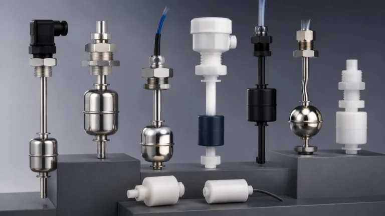
In the landscape of industrial automation and process control, the flowline level sensor serves as a critical component for monitoring and managing liquid levels in tanks, reservoirs, and open channels. These sensors are engineered to provide real-time data, ensuring operational safety, inventory accuracy, and process efficiency. Whether the application involves corrosive chemicals, wastewater treatment, or high-viscosity oils, selecting the appropriate sensing technology is fundamental to achieving reliable performance.
Industrial level measurement is not a one-size-fits-all discipline. Factors such as the physical properties of the medium, ambient environmental conditions, and the specific geometry of the vessel dictate which measurement principle will yield the most accurate results. This guide explores the primary technologies used in flowline level sensing, offering technical insights into their operation, selection, and installation.
Measurement Principles of Level Sensors
Before selecting a flowline level sensor, it is essential to understand the physics behind the most common measurement technologies. Modern industrial sensors typically utilize ultrasonic, radar, or hydrostatic principles.
Ultrasonic Level Measurement
Ultrasonic sensors operate on the "Time-of-Flight" (ToF) principle. The sensor emits a high-frequency acoustic pulse from its transducer. This pulse travels through the air, reflects off the surface of the liquid, and returns to the transducer. By measuring the time interval between the emission and the reception of the echo, and knowing the speed of sound in air (approximately 343 m/s or 1,125 ft/s at 20°C), the device calculates the distance to the liquid surface.
* Advantages: Non-contact measurement, no moving parts, and relatively low cost.
* Limitations: Performance can be affected by heavy foam, extreme turbulence, or significant temperature gradients that alter the speed of sound.
Radar (Microwave) Level Measurement
Similar to ultrasonic sensors, radar sensors use the ToF principle but employ electromagnetic waves instead of sound. These waves travel at the speed of light. Radar sensors can be non-contact (emitting waves through the air) or guided-wave (where the pulse travels along a probe or cable).
* Advantages: Unaffected by vacuum, high pressure, dust, or vapors. High precision (often within ±2 mm).
* Limitations: Generally more expensive than ultrasonic options; non-contact radar requires a clear line of sight to the surface.
Hydrostatic Level Measurement
Hydrostatic sensors are pressure-based. They measure the pressure exerted by the liquid column above the sensor. According to Pascal’s Law, the pressure at a specific depth is proportional to the height of the liquid and its specific gravity. For atmospheric tanks, a submersible pressure transmitter or an externally mounted sensor at the bottom of the tank is used.
* Advantages: Simple installation, highly reliable for deep wells or underground tanks, and unaffected by surface foam or turbulence.
* Limitations: Accuracy depends on a constant liquid density; if the medium’s density changes due to temperature or composition, the reading will drift.
Key Selection Criteria for Flowline Level Sensors
Choosing the right sensor requires a systematic evaluation of the application's technical requirements. Engineers must consider the following variables to ensure the longevity and accuracy of the instrument.
1. Media Characteristics
The chemical compatibility of the sensor’s wetted parts (the materials in contact with the liquid) is paramount. For corrosive media like sulfuric acid or sodium hydroxide, sensors made from PVDF, PTFE, or high-grade stainless steel are required. Additionally, consider if the liquid is prone to coating or scaling, as this can interfere with mechanical or contact-based sensors.
2. Measurement Range and Accuracy
Define the maximum and minimum levels to be measured. Ultrasonic sensors have a "dead zone" (blocking distance) near the transducer where measurement is impossible, typically ranging from 10 cm to 50 cm (4 in to 20 in). Ensure the sensor's range exceeds the tank height while accounting for these dead zones.
3. Environmental Conditions
Temperature and pressure significantly impact sensor performance. Standard ultrasonic sensors are often rated up to 60°C or 80°C (140°F to 176°F), whereas radar sensors can handle much higher temperatures and pressures. If the sensor is installed outdoors, ensure it has an appropriate Ingress Protection (IP) rating, such as IP67 or IP68, to withstand moisture and dust.
4. Output and Integration
Most industrial flowline level sensors provide a 4-20 mA analog output, often with HART protocol for digital communication. For modern automation systems, Modbus RTU or Profibus may be required to integrate the sensor directly into a PLC or SCADA system. For detailed technical specifications on various output configurations, engineers can visit the Main Page of professional manufacturers to review product options and application support.
Comparative Analysis of Measurement Technologies
The following table provides a quick reference for comparing the three primary technologies discussed.
| Feature | Ultrasonic | Radar (Non-Contact) | Hydrostatic |
| :— | :— | :— | :— |
| Measurement Type | Non-contact | Non-contact | Contact (Pressure) |
| Accuracy | ±0.25% to ±0.5% | ±2 mm to ±5 mm | ±0.1% to ±0.5% |
| Media Influence | Affected by foam/vapor | Unaffected by vapor | Affected by density changes |
| Typical Range | 0.25 m to 15 m | 0.5 m to 70 m+ | 1 m to 200 m+ |
| Relative Cost | Low to Moderate | Moderate to High | Moderate |
| Best Use Case | Water/Wastewater | Chemical/Oil Storage | Deep Wells/Vented Tanks |
Installation and Engineering Best Practices
Proper installation is as critical as sensor selection. Even the most advanced flowline level sensor will fail if it is positioned incorrectly.
1. Avoid Obstructions: For ultrasonic and radar sensors, the signal beam spreads as it travels (the beam angle). Ensure there are no ladders, pipes, or agitators within the signal cone, as these will cause "false echoes."
2. Perpendicularity: The sensor must be mounted perfectly perpendicular to the liquid surface. A tilt of even a few degrees can cause the signal to reflect away from the receiver, leading to signal loss.
3. Nozzle Height and Diameter: If mounting the sensor on a nozzle, the nozzle must be short enough and wide enough to prevent the signal from reflecting off the nozzle walls before reaching the tank interior.
4. Turbulence Management: In tanks with heavy agitation, a stilling well (a vertical pipe installed in the tank) can be used to provide a calm surface for the sensor to measure. This is particularly effective for both ultrasonic and radar technologies.
5. Submersible Positioning: For hydrostatic sensors, the transmitter should be located away from intake or discharge flows to avoid dynamic pressure errors. It should also be secured to prevent movement in turbulent conditions.
Application-Specific Considerations
Different industries present unique challenges for level sensing. Understanding these nuances helps in refining the sensor configuration.
Water and Wastewater Treatment
In these applications, sensors often face humidity, condensation, and fluctuating temperatures. Ultrasonic sensors are the industry standard here due to their cost-effectiveness. However, in sewage lift stations where grease or foam is prevalent, hydrostatic sensors or radar may be preferred to avoid surface-related interference.
Chemical Processing
Chemical tanks often contain aggressive vapors. Radar sensors are superior in these environments because electromagnetic waves are not attenuated by chemical vapors. Furthermore, the non-contact nature of radar prevents the corrosive medium from damaging the sensitive electronics of the instrument.
Oil and Gas
In the oil and gas sector, sensors must often meet explosion-proof (Ex-d) or intrinsically safe (Ex-ia) standards. Because hydrocarbons can have low dielectric constants, radar sensors must be carefully calibrated to ensure they can detect the weak reflection from the oil surface.
Maintenance and Operational Longevity
While modern electronic sensors are designed for minimal maintenance, periodic checks are necessary to ensure continued accuracy.
* Visual Inspection: Regularly check for buildup on the transducer face of ultrasonic or radar sensors. Even a thin layer of condensation or crystallized chemicals can degrade signal strength.
* Calibration Verification: Perform a "zero and span" check annually. This involves comparing the sensor's reading against a manual tape measurement at both low and high levels.
* Cable Integrity: For hydrostatic sensors, ensure the vent tube in the cable is not kinked or blocked by moisture. A blocked vent tube will prevent the sensor from compensating for changes in atmospheric pressure, leading to significant errors.
Frequently Asked Questions
Q: Can an ultrasonic flowline level sensor measure solids?
A: Yes, but with limitations. Solids like grain or plastic pellets do not reflect sound as efficiently as liquids and often have an uneven surface (angle of repose). Higher power sensors and specific mapping software are usually required for solid applications.
Q: What is the dielectric constant, and why does it matter for radar?
A: The dielectric constant (Er) is a measure of a material's ability to reflect electromagnetic energy. Liquids with a high Er (like water, Er ≈ 80) reflect radar waves very well. Liquids with a low Er (like oils or solvents, Er < 2.0) reflect very little energy, requiring more sensitive radar units or guided-wave probes.
Q: How do I handle foam on the liquid surface?
A: Foam absorbs ultrasonic pulses and scatters radar waves. If the foam is light and airy, radar can often see through it to the liquid below. If the foam is thick and dense, a hydrostatic pressure sensor is usually the most reliable solution as it is unaffected by surface conditions.
Q: What is the difference between a level sensor and a level switch?
A: A level sensor provides continuous measurement (e.g., 0-100% full), while a level switch provides a discrete signal at a specific point (e.g., "tank is full" or "tank is empty"). Switches are often used for overfill protection or pump control logic.
By carefully considering the measurement principle, environmental constraints, and installation requirements, engineers can successfully implement a flowline level sensor solution that provides accurate and reliable data for years of service. For those seeking specific product data sheets or customized OEM solutions, consulting with a professional manufacturer is the recommended next step in the procurement process.