Pressure Sensor for Water Level Measurement
Pressure Sensor for Water Level Measurement
In industrial process control and water management, the ability to accurately determine the volume or height of a liquid is fundamental. Among the various technologies available, the use of a pressure sensor for water level measurement—specifically through the hydrostatic principle—remains one of the most reliable and cost-effective methods. This approach is widely adopted across water treatment facilities, chemical processing plants, and deep-well monitoring due to its robustness and ease of integration into existing automation systems.
As a professional manufacturer of industrial level measurement instruments, Welk provides a range of solutions tailored to these demanding environments. Understanding the underlying physics, selection criteria, and installation nuances is essential for engineers and procurement professionals seeking to optimize their liquid monitoring infrastructure. For those evaluating specific hardware configurations, the Main Page of the manufacturer’s technical site offers a comprehensive overview to review product options and application support.
Understanding the Hydrostatic Principle
The fundamental principle behind using a pressure sensor for water level measurement is hydrostatic pressure. Hydrostatic pressure is the pressure exerted by a fluid at equilibrium at a given point within the fluid, due to the force of gravity. This relationship is mathematically expressed by the formula:
P = ρ × g × h
Where:
- P is the hydrostatic pressure (typically measured in Pascals or bar).
- ρ (rho) is the density of the liquid (for pure water, approximately 1,000 kg/m³).
- g is the acceleration due to gravity (approximately 9.81 m/s²).
- h is the height of the liquid column above the sensor.
Because gravity and the density of the liquid are generally constant in most water-based applications, the pressure measured by the sensor is directly proportional to the height of the water. By measuring the pressure at the bottom of a tank or at a specific depth in a borehole, the instrument can calculate the exact level. This method is "contact-based," meaning the sensor or its diaphragm must be in physical contact with the media or the pressure exerted by it.
Types of Pressure Sensors for Water Level Measurement
While the principle remains the same, the physical configuration of the sensor varies depending on the installation environment. There are two primary categories of pressure-based level transmitters.
1. Submersible Level Transmitters
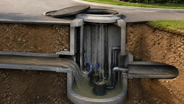
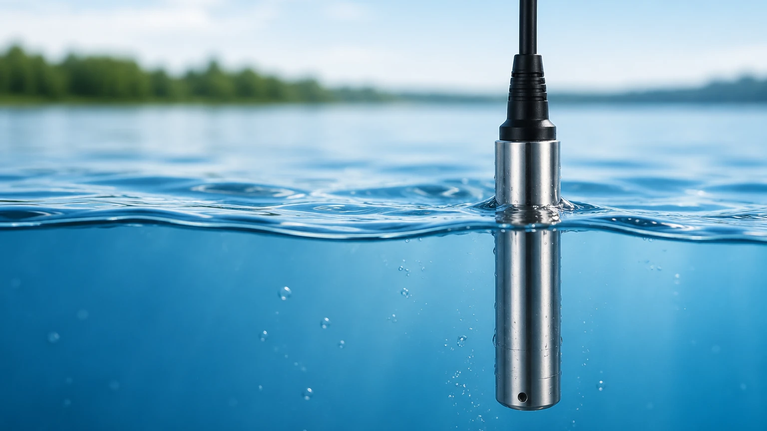
Submersible sensors are designed to be lowered directly into the liquid. The entire unit, including the sensing element and electronics, is housed in a waterproof (IP68) enclosure, typically made of 316L stainless steel or specialized plastics for corrosive environments. These are ideal for open reservoirs, deep wells, and wastewater lift stations.
2. External (Dry-Mount) Pressure Transmitters
These sensors are mounted on the outside of a tank, usually via a threaded or flanged connection at the bottom. The water enters the sensor chamber through the process connection, and the pressure is measured against a diaphragm. These are preferred for closed tanks or vessels where internal access is limited or where the liquid is under additional headspace pressure.
3. Differential Pressure (DP) Transmitters
In pressurized tanks, the total pressure at the bottom is the sum of the liquid's hydrostatic pressure and the gas pressure in the headspace. A standard pressure sensor would provide an incorrect reading in this scenario. A differential pressure sensor measures the difference between the bottom pressure and the top pressure, effectively "canceling out" the gas pressure to isolate the hydrostatic level.
Technical Selection Criteria for Industrial Applications
Choosing the correct pressure sensor for water level measurement requires a detailed analysis of the process conditions. Selecting an inappropriate sensor can lead to drift, premature failure, or inaccurate data.
Measuring Range and Overpressure
The sensor’s range should closely match the maximum expected water level. For example, a 10-meter deep tank should ideally use a sensor rated for 0–1 bar (approximately 10.2 meters of water column). Using a sensor with a range that is too high (e.g., 0–10 bar) will result in poor resolution at lower levels. Additionally, engineers must consider "overpressure" ratings—the maximum pressure a sensor can withstand without damage, which is critical in systems prone to water hammer or surges.
Material Compatibility
While 316L stainless steel is the standard for clean water, other materials are necessary for different media:
- Wastewater: May require a flush diaphragm to prevent clogging from solids.
- Seawater: Requires titanium or high-grade plastic housings to prevent galvanic corrosion.
- Chemicals: May necessitate Hastelloy diaphragms or PTFE coatings.
Accuracy and Stability
Industrial-grade sensors typically offer accuracy ranging from 0.1% to 0.5% of the full scale. Long-term stability is also vital; high-quality sensors use piezoresistive or ceramic thick-film technology to ensure the reading does not drift over years of operation.
Signal Output and Integration
Most B2B applications utilize the 4-20mA analog signal due to its reliability over long cable runs and its inherent noise immunity. However, digital protocols like RS485 Modbus or HART are increasingly common for smart water management, allowing for remote diagnostics and multiple parameter reporting.
Installation Best Practices and Cable Management
The longevity of a pressure sensor for water level measurement is often determined by how it is installed. Even the most accurate sensor will fail if environmental factors are ignored.
Atmospheric Pressure Compensation
For an accurate level reading, the sensor must account for changes in atmospheric pressure. Submersible sensors achieve this through a "vented cable." This cable contains a small capillary tube that allows the internal side of the sensor diaphragm to be exposed to the ambient air pressure. It is crucial that this vent tube is kept clear and protected from moisture using a desiccant filter or a specialized junction box. If moisture enters the vent tube, it can lead to internal corrosion or measurement errors.
Avoiding Turbulence and Physical Damage
In tanks with agitators or in fast-flowing channels, the sensor should be placed inside a "stilling well" (a perforated pipe). This protects the sensor from the physical force of moving water and prevents signal "noise" caused by turbulence. For deep-well applications, the sensor should be securely anchored to prevent it from swinging and hitting the well casing.
Cable Support
The weight of the cable in deep-well installations can put significant strain on the internal wiring. Using a cable clamp or a specialized strain-relief grip at the top of the well is mandatory to prevent the cable from stretching or snapping.
Limitations and Environmental Factors
While hydrostatic pressure is a versatile technology, it has specific limitations that engineers must account for during the design phase.
Density Variations
As noted in the formula $P = \rho gh$, the sensor measures weight, not volume. If the density ($
ho$) of the liquid changes—due to temperature fluctuations or changes in chemical concentration—the level reading will shift even if the actual height of the water remains constant. In applications with wide temperature swings, temperature-compensated sensors or secondary temperature probes are necessary to calculate the corrected density.
Media Buildup and Clogging
In wastewater or sludge applications, grease and solids can accumulate on the sensor diaphragm. This buildup adds weight or restricts movement, leading to false high or low readings. In these cases, a flush-diaphragm pressure sensor or a non-contact ultrasonic sensor might be a more suitable alternative.
Comparison of Level Measurement Technologies
To help in the selection process, the following table compares hydrostatic pressure sensors with other common technologies used in water level measurement.
| Technology | Principle | Best For | Limitations |
| :— | :— | :— | :— |
| Hydrostatic Pressure | Pressure at depth | Deep wells, vented tanks, wastewater | Sensitive to density changes |
| Ultrasonic | Sound wave reflection | Non-contact, clean liquids | Affected by foam, steam, and wind |
| Radar (80GHz) | Microwave reflection | High precision, aggressive media | Higher initial cost |
| Magnetic Gauge | Buoyancy/Float | Visual indication, high temp | Moving parts can stick; limited range |
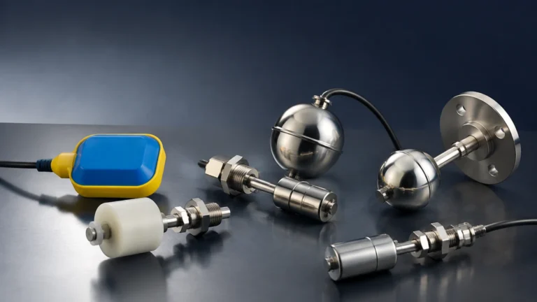
| Float Switch | Mechanical buoyancy | Point level (high/low alarm) | No continuous measurement |
Maintenance and Troubleshooting FAQs
Q: How often should a pressure sensor for water level measurement be calibrated?
A: For most industrial applications, an annual calibration check is recommended. However, in critical infrastructure or high-fouling environments, bi-annual checks may be necessary to ensure zero-point stability.
Q: Can I cut the vented cable to a shorter length?
A: Yes, most cables can be shortened, but extreme care must be taken not to block or crimp the internal vent tube. Always use the manufacturer-recommended junction box to terminate the cable.
Q: What happens if the sensor is installed in a pressurized tank?
A: A standard submersible sensor will measure the sum of the liquid pressure and the gas pressure, leading to an over-reading. In this scenario, a differential pressure (DP) transmitter must be used to subtract the headspace pressure.
Q: How do I protect the sensor from lightning strikes?
A: Since these sensors are often located in large outdoor tanks or deep wells, they are susceptible to surges. Using a surge protector at the control panel and selecting sensors with built-in lightning protection (transient voltage suppression) is highly recommended.
Conclusion
The pressure sensor for water level measurement remains a cornerstone of industrial liquid monitoring due to its straightforward physics and adaptable design. By carefully considering the media properties, installation environment, and the need for atmospheric compensation, engineers can implement a solution that provides years of reliable service.
Welk continues to innovate in this space, offering customized OEM/ODM services to meet specific project requirements, from simple water storage to complex industrial automation. For detailed specifications and to explore the full range of level measurement instruments, professionals are encouraged to Review product options and application support on the official manufacturer website. Proper selection and installation not only ensure data accuracy but also significantly reduce the total cost of ownership by minimizing maintenance and downtime in critical water management operations.
Download Pressure Sensor for Water Level Measurement as a PDF