Flush Mount Pressure Transducer
Flush Mount Pressure Transducer
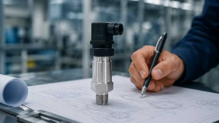
In industrial process control and level measurement, the physical interface between a sensor and the media it measures is a critical engineering consideration. Standard pressure transmitters typically utilize a small internal cavity or a narrow pressure port to channel fluid toward a sensing diaphragm. While effective for clean liquids and gases, these designs frequently fail when applied to viscous, particulate-laden, or hygienic media. The flush mount pressure transducer addresses these challenges by positioning the sensing diaphragm directly at the process interface, eliminating the recessed cavity where media could otherwise accumulate, solidify, or ferment.
For engineers and plant operators, selecting a flush mount pressure transducer is often a necessity driven by the physical properties of the process fluid. This guide examines the underlying principles, selection criteria, and practical installation requirements for these specialized instruments.
Measurement Principles of Flush Mount Transducers
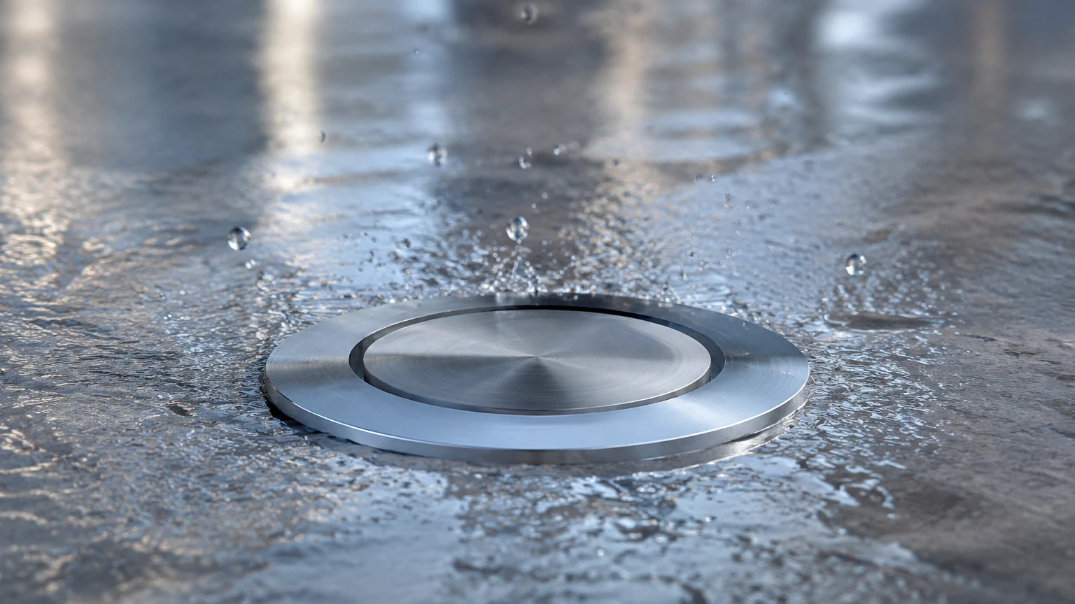
To understand why a flush mount design is selected, one must first understand how it converts physical pressure into an electrical signal. Unlike standard sensors, the diaphragm of a flush mount pressure transducer is welded directly to the front of the process connection, making it perfectly level with the interior wall of the pipe or tank.
The Sensing Element
Most modern flush mount transducers utilize one of two primary sensing technologies:
1. Piezoresistive Sensors: These involve a silicon or metal foil strain gauge bonded to the back of the diaphragm. When process pressure deforms the diaphragm, the electrical resistance of the gauge changes proportionally. This change is processed by internal electronics into a standard industrial signal, such as 4-20mA or 0-10V.
2. Capacitive Sensors: In this design, the diaphragm acts as one plate of a capacitor. As pressure moves the diaphragm closer to a fixed internal electrode, the capacitance changes. Capacitive sensors are often preferred for very low-pressure ranges due to their high sensitivity and robustness against overpressure events.
The Role of Fill Fluids
Because the sensing element is often located slightly behind the flush diaphragm for protection, a transmission fluid (typically silicone oil or food-grade vegetable oil) is used to transfer the mechanical force from the outer diaphragm to the internal sensor. This hydraulic link ensures that the pressure is transmitted accurately without requiring the sensitive electronics to be in direct contact with harsh process media.
Key Evaluation Criteria for Selection
Selecting the correct flush mount pressure transducer requires a detailed analysis of the process environment. Failure to match the sensor materials to the media can lead to diaphragm rupture or signal drift.
Material Compatibility
The diaphragm is the most vulnerable component of the transducer. It must be thin enough to remain sensitive to pressure changes but durable enough to withstand chemical corrosion and mechanical wear. Common materials include:
* 316L Stainless Steel: The standard for water treatment and general industrial applications.
* Hastelloy C: Required for highly corrosive chemical environments where stainless steel would pit or corrode.
* Tantalum: Used for extreme acid applications.
* Ceramic: Offers excellent abrasion resistance for slurries, though it is more brittle than metal diaphragms.
Technical Specification Table
| Parameter | Description | Typical Industrial Range |
| :— | :— | :— |
| Pressure Range | The maximum and minimum pressure the sensor can measure. | 0.1 bar to 600 bar (1.5 to 8700 psi) |
| Accuracy | The deviation from the true pressure value. | 0.1% to 0.5% of Full Scale |
| Operating Temperature | The temperature range of the process media. | -40°C to +150°C (Special cooling for higher) |
| Output Signal | The electrical format for control system integration. | 4-20mA, 0-5V, Modbus RTU, HART |
| Ingress Protection | The sensor's resistance to dust and moisture. | IP65, IP67, or IP68 for submersion |
Process Connections
Flush mount transducers do not use standard NPT or BSP threads in the same way recessed sensors do. They often require specialized "weld-on" sockets or hygienic couplings (such as Tri-Clamp or Varivent) to ensure the diaphragm remains truly flush with the vessel wall. For comprehensive technical data on various connection types, engineers may Review product options and application support to ensure compatibility with existing tank geometries.
Industrial Applications and Use Cases
The decision to move from a standard transmitter to a flush mount pressure transducer is typically dictated by the presence of solids or high viscosity.
Food and Beverage Processing
In the dairy and beverage industry, hygiene is paramount. Standard recessed sensors create "dead zones" where milk or juice can collect and harbor bacterial growth. A flush mount transducer, particularly one with a hygienic Tri-Clamp fitting, allows for Clean-in-Place (CIP) and Steam-in-Place (SIP) sterilization without removing the sensor. The smooth surface ensures that no organic material remains after a cleaning cycle.
Wastewater and Sludge Management
Wastewater often contains fibrous materials, grit, and high concentrations of suspended solids. In these environments, a standard pressure port would clog within hours. Flush mount sensors allow the moving fluid to naturally "wipe" the diaphragm clean, maintaining accurate level and pressure readings in grit chambers and sludge digestion tanks.
Pulp and Paper Industry
The paper-making process involves thick slurries of wood fiber and water. These fibers easily bridge across small openings. Flush mount transducers are installed in headboxes and pulp lines to monitor pressure without the risk of the pulp hardening inside the sensor port and providing a false reading.
Installation Considerations and Best Practices
Proper installation is as important as selecting the right sensor. Because the diaphragm is exposed and thin (often only 0.05mm to 0.1mm thick), it is susceptible to damage during handling and mounting.
1. Avoid Diaphragm Contact: Never touch the flush diaphragm with fingers or tools. Even a slight dent can change the tension of the metal and ruin the factory calibration.
2. Correct Torque: When installing threaded flush mount sensors, follow the manufacturer's torque specifications exactly. Over-tightening can stress the sensor housing and cause a zero-point shift in the signal.
3. Orientation: For liquid level measurement in tanks, the sensor should ideally be installed on the side of the tank near the bottom. If installed on the very bottom, ensure there is a slight pitch to prevent sediment from settling directly on the diaphragm surface over time.
4. Welding Sockets: If using a weld-on adapter, ensure the welding process does not warp the socket. A warped socket will prevent the transducer from sealing properly or may put uneven pressure on the diaphragm.
Common Risks and Limitations
While highly versatile, flush mount pressure transducers are not a universal solution for every application. Engineers must be aware of specific limitations:
* Mechanical Damage: Because the diaphragm is flush, it is exposed to the full force of the process flow. In high-velocity lines containing abrasive sand or rocks, the diaphragm can be eroded or punctured. In such cases, a protective shield or a different measurement technology, like a non-contact radar level meter, might be more appropriate.
* Thermal Shock: Rapid changes in process temperature (e.g., during a cold water flush after a steam cleaning cycle) can cause the fill fluid inside the sensor to expand or contract faster than the housing, leading to temporary measurement errors or "thermal drift."
* Pressure Spikes: Water hammer or sudden valve closures can create pressure spikes that exceed the burst pressure of the thin flush diaphragm. Installing the sensor away from quick-closing valves or using snubbers (though difficult with flush designs) is a necessary precaution.
Frequently Asked Questions (FAQ)
Q: Can a flush mount pressure transducer be used for vacuum measurement?
A: Yes, many flush mount sensors are designed to measure both positive pressure and vacuum (compound ranges). However, you must ensure the internal fill fluid is degassed and rated for vacuum service to prevent bubbling at low pressures.
Q: How do I clean a flush diaphragm if it becomes coated?
A: If the media is particularly sticky, the diaphragm can be cleaned using a soft cloth and a compatible solvent. Never use a wire brush, screwdriver, or any sharp object, as the diaphragm is extremely thin and easily punctured.
Q: What is the difference between a flush mount transducer and a chemical seal?
A: A flush mount transducer is an integrated unit where the diaphragm is part of the sensor body. A chemical seal (or diaphragm seal) is often a separate component that is attached to a standard pressure transmitter via a capillary tube. Flush mount transducers are generally more compact and have faster response times.
Q: Is a flush mount sensor required for clean water?
A: Generally, no. For clean, non-viscous water, a standard recessed pressure transmitter is more cost-effective and less prone to accidental diaphragm damage. Flush mount designs are specifically intended for "difficult" media.
Conclusion and Next Steps
The flush mount pressure transducer is a vital tool for maintaining accuracy and hygiene in challenging industrial environments. By eliminating the internal cavities found in traditional sensors, these devices prevent clogging and bacterial growth, ensuring long-term reliability in wastewater, chemical, and food processing applications.
When planning a new installation or upgrading an existing system, engineers should confirm the chemical compatibility of the diaphragm material, the required pressure range, and the specific process connection needed for a flush fit. For detailed technical specifications and to explore a range of industrial measurement solutions, visit the Main Page to consult with application specialists and review available hardware configurations.