Foam Thickness Measurement
Foam Thickness Measurement
In industrial process control, foam thickness measurement represents one of the most complex challenges for instrumentation engineers. Unlike stable liquid surfaces, foam is a dynamic, multi-phase medium consisting of gas bubbles trapped within a liquid film. In sectors such as wastewater treatment, chemical processing, food and beverage production, and pharmaceutical manufacturing, accurately determining the thickness of a foam layer—and the location of the underlying liquid interface—is critical for preventing vessel overflow, protecting downstream equipment, and optimizing the use of anti-foaming agents.
Effective foam management requires a deep understanding of how different measurement technologies interact with various foam densities and dielectric properties. This guide explores the principles of foam detection and provides a technical framework for selecting and installing the appropriate level measurement instruments.
Measurement Principles for Foam and Interfaces
To achieve accurate foam thickness measurement, an instrument must ideally identify two distinct points: the top of the foam layer (the gas-foam interface) and the bottom of the foam layer (the foam-liquid interface). The difference between these two values defines the foam thickness.
Radar Level Measurement (Non-Contact)
Non-contact radar transmitters, particularly those operating at high frequencies such as 80GHz, emit electromagnetic pulses toward the product surface. When these pulses encounter a change in the dielectric constant ($ε_r$), a portion of the energy is reflected back to the sensor.
* Surface Detection: High-frequency radar is excellent at detecting the top of a foam layer if the foam is sufficiently dense or has a high dielectric constant. However, very light, airy foam may be transparent to certain radar frequencies, causing the sensor to read the liquid level instead of the foam surface.
* Signal Processing: Modern radar units use advanced algorithms to filter out "noise" and identify the primary reflection. In foam applications, the signal-to-noise ratio is critical, as foam tends to scatter and attenuate electromagnetic energy.
Guided Wave Radar (GWR)
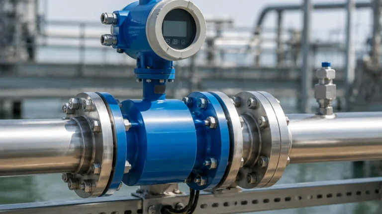
Guided Wave Radar utilizes a physical probe (rod or cable) to guide the microwave pulse directly to the process medium. This technology is often the preferred choice for foam thickness measurement because it can detect both the foam surface and the liquid interface.
* The Interface Principle: When the pulse hits the foam, a partial reflection occurs (representing the foam top). The remaining energy continues down the probe through the foam. When it hits the liquid—which typically has a much higher dielectric constant than foam—a second, stronger reflection is generated. By measuring the time-of-flight for both reflections, the transmitter calculates both the total level and the foam thickness.
Ultrasonic Level Measurement
Ultrasonic sensors use sound waves to measure distance. While effective for many liquid applications, they face significant hurdles in foam thickness measurement. Foam is an excellent acoustic insulator; the air-filled bubbles absorb and scatter sound energy, often leading to a total loss of signal (signal attenuation). Ultrasonic technology is generally only recommended for very thin, dense foams where the surface is relatively solid.
Capacitance and Conductivity
Capacitance probes measure the change in electrical capacitance between the probe and the vessel wall. As foam rises, it changes the dielectric environment around the probe. Conductivity switches, on the other hand, rely on the foam's ability to complete an electrical circuit. These are often used as point-level alarms to detect when foam has reached a maximum allowable height, rather than providing continuous thickness measurement.
Selecting Technology for Foam Applications
Choosing the right instrument depends heavily on the physical characteristics of the foam. Foam is generally categorized as "dry" (high gas content, low density) or "wet" (high liquid content, high density).
| Foam Characteristic | Recommended Technology | Rationale |
| :— | :— | :— |
| Light / Dry Foam | High-Frequency Non-contact Radar | Higher frequencies (80GHz) are more likely to reflect off light surfaces. |
| Dense / Wet Foam | Guided Wave Radar (GWR) | Excellent for penetrating foam to find the liquid interface while still detecting the foam top. |
| Highly Conductive Foam | Conductivity Switches | Best for high-level overflow protection in aggressive chemical processes. |
| Unstable / Fast-Moving Foam | High-Speed Radar | Fast sampling rates are required to track rapid changes in foam height. |
For engineers looking to integrate these technologies into their control systems, it is advisable to Review product options and application support to ensure the selected hardware matches the specific dielectric properties of the process media.
Installation Considerations and Best Practices
Proper installation is as important as technology selection when dealing with foam thickness measurement. Even the most advanced sensor will fail if placed in a position where process dynamics interfere with signal return.
1. Nozzle Geometry
For non-contact radar and ultrasonic sensors, the mounting nozzle should be as short as possible. Long, narrow nozzles can create internal reflections (ringing) that mask the signal from the foam surface, especially if the foam is light and provides a weak return signal.
2. Avoiding Obstructions
Foam measurement requires a clear "view" of the surface. Internal vessel structures such as agitators, ladders, or heating coils can create false echoes. While software mapping can sometimes ignore these obstructions, the turbulence caused by agitators often creates uneven foam distribution, leading to inconsistent readings.
3. Stilling Wells and Bypass Chambers
In applications with heavy turbulence or extremely light foam, installing the sensor in a stilling well or an external bypass chamber can stabilize the surface. For Guided Wave Radar, a coaxial probe design acts as its own stilling well, protecting the signal from turbulence and foam spray while providing a concentrated path for the microwave pulse.
4. Condensation and Build-up
Foam often leaves a residue on the sensor face or probe. Welk instruments are frequently designed with PTFE or other non-stick coatings to minimize build-up. In cases of heavy condensation, a radar sensor with a flat-face antenna or an integrated air purge system may be necessary to keep the lens clear.
Limitations of Foam Measurement Technologies
It is important to acknowledge the factual boundaries of current measurement physics. No single technology is a universal solution for every foam type.
* Dielectric Sensitivity: If the dielectric constant of the foam is too close to that of the gas space above it (typically $ε_r ≈ 1$), non-contact radar will not "see" the foam. Conversely, if the foam is extremely dense and has a dielectric constant close to the liquid, the sensor may not be able to distinguish the interface between the foam and the liquid.
* Environmental Factors: High pressure and extreme temperatures can alter the density of the gas space, affecting the speed of sound for ultrasonic sensors. While radar is less affected by these factors, extreme steam or heavy dust can still attenuate the signal over long distances.
* Vessel Shape: In small or narrow vessels, the beam spread of the sensor may interact with the walls. Using higher frequency radar (80GHz) provides a narrower beam angle (typically 3° to 6°), which helps avoid wall interference.
Frequently Asked Questions (FAQ)
Q: Can a standard hydrostatic pressure transmitter measure foam thickness?
A: Generally, no. Hydrostatic pressure transmitters measure the "head" or weight of the liquid. Since foam is mostly gas, it has very little mass. A pressure transmitter will accurately measure the liquid level but will be almost entirely blind to the foam layer above it.
Q: How does foam density affect radar accuracy?
A: As foam density increases, its dielectric constant typically increases, providing a stronger reflection for radar sensors. However, very thick, wet foam can also absorb more energy, which might reduce the signal strength reaching the liquid interface in GWR applications.
Q: Is it possible to measure foam thickness in a pressurized tank?
A: Yes. Radar technology is ideal for pressurized environments because electromagnetic waves do not require a medium for travel and are largely unaffected by changes in vapor space pressure. Guided Wave Radar is particularly effective in high-pressure separators used in the oil and gas industry.
Q: What maintenance is required for foam level sensors?
A: Maintenance depends on the "stickiness" of the foam. For non-contact sensors, periodic cleaning of the antenna lens may be required if splashing occurs. For GWR, the probe should be inspected for material build-up that could cause signal bridging, especially in the transition zone near the top of the probe.
Conclusion for Process Engineers
Accurate foam thickness measurement is essential for maintaining process efficiency and safety. By selecting a technology based on the dielectric properties and density of the foam, and by adhering to strict installation guidelines, engineers can mitigate the risks associated with foam-over events and equipment damage. For those seeking detailed specifications or customized OEM/ODM solutions for industrial level measurement, visiting the Main Page provides access to a comprehensive range of radar, ultrasonic, and hydrostatic instruments designed for challenging industrial environments.
When evaluating a new application, always confirm the minimum and maximum foam thickness expected, the dielectric constant of the base liquid, and the presence of any tank internals that could interfere with the measurement signal. This proactive approach ensures the longevity and reliability of the instrumentation system.