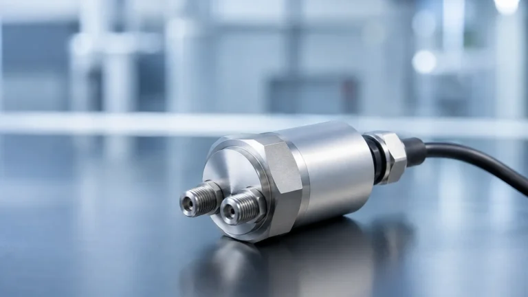
Flow Meter and Totalizer
Flow Meter and Totalizer
In industrial process control, the ability to monitor fluid movement is fundamental to operational efficiency, safety, and billing accuracy. While a flow meter provides a real-time measurement of the velocity or volume of a fluid passing through a specific point, the totalizer serves as the "odometer" of the system, calculating the cumulative volume over a specific period. The integration of a flow meter and totalizer is essential in applications ranging from municipal water treatment to complex chemical dosing and oil and gas distribution.
For engineers and plant managers, selecting the right combination requires an understanding of both the physical principles of flow measurement and the electronic logic used to aggregate those measurements into a totalized value. This guide explores the technical foundations, selection criteria, and installation best practices for these critical instruments.
Measurement Principles of Flow Meters
Before a totalizer can provide an accurate cumulative reading, the primary flow sensor must capture precise data. Industrial flow meters utilize various physical principles depending on the fluid properties and the environment.
Electromagnetic Flow Meters
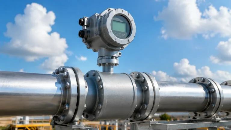
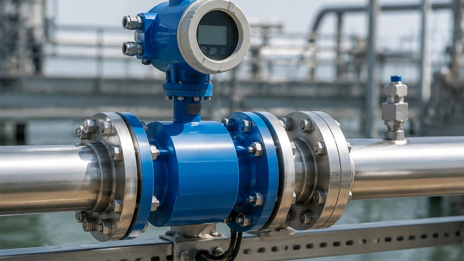
Electromagnetic meters, often called magmeters, operate based on Faraday’s Law of Electromagnetic Induction. When a conductive liquid flows through a magnetic field generated by the meter, it creates a voltage proportional to the velocity of the liquid.
* Application: Best for conductive liquids like water, wastewater, and slurries.
* Advantage: No moving parts and no pressure drop.
* Constraint: Cannot measure non-conductive fluids like oils or deionized water.
Ultrasonic Flow Meters
Ultrasonic technology typically uses the "transit-time" principle. Two transducers are mounted on the pipe, sending and receiving ultrasonic signals. The difference in the time it takes for the signal to travel upstream versus downstream is proportional to the flow velocity.
* Application: Clean liquids in large pipes; often used in HVAC and water distribution.
* Advantage: Non-intrusive (clamp-on models available), meaning no process downtime for installation.
* Constraint: Requires a relatively clean fluid without excessive air bubbles or suspended solids that could scatter the signal.
Differential Pressure (DP) Meters
DP meters use a primary element, such as an orifice plate or a Venturi tube, to create a constriction in the flow path. According to Bernoulli’s equation, the pressure drop across this constriction is proportional to the square of the flow rate.
* Application: Steam, gases, and high-pressure liquids.
* Advantage: Well-understood technology with long-standing industry standards.
* Constraint: Causes a permanent pressure loss in the system.
Open Channel Flow (Level-Based)
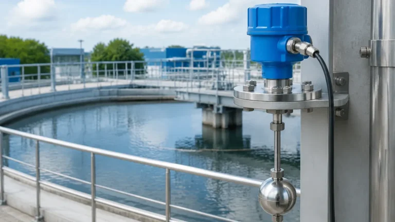
In many water treatment scenarios, flow occurs in open channels rather than closed pipes. Here, level measurement instruments—such as radar or ultrasonic level sensors—are used in conjunction with a flume or weir. The level of the liquid at a specific point is converted into a flow rate based on the geometry of the structure. This is an area where Welk’s expertise in radar and ultrasonic level sensors directly supports flow calculation.
The Function of the Totalizer
The totalizer is the electronic component that processes the signal from the flow meter. It performs a mathematical integration of the flow rate over time:
$$\text{Total Volume} = \int_{t1}^{t2} Q(t) \, dt$$
Where $Q$ is the instantaneous flow rate and $t$ is time. In modern digital systems, this is handled via high-speed sampling. Totalizers can be integrated directly into the flow meter’s transmitter or exist as a separate panel-mounted unit.
Signal Types for Totalization
1. Pulse Output: The flow meter sends a pulse for every unit of volume (e.g., 1 pulse per 10 liters). The totalizer simply counts these pulses. This is often the most accurate method for totalization as it avoids analog conversion errors.
2. Analog Signal (4-20mA): The meter sends a current signal proportional to the flow rate. The totalizer samples this current and integrates it. While common, this method is susceptible to slight inaccuracies if the signal scaling or sampling rate is not perfectly calibrated.
3. Digital Communication: Using protocols like Modbus RTU, HART, or Profibus, the totalizer receives digital data packets directly from the meter, ensuring zero loss of precision during transmission.
Selection Criteria for Flow Meter and Totalizer Systems
Choosing a flow meter and totalizer requires a detailed analysis of the process conditions. Use the following table as a preliminary selection guide for common industrial technologies:
| Technology | Fluid Type | Typical Accuracy | Pipe Size Range | Maintenance Needs |
| :— | :— | :— | :— | :— |
| Electromagnetic | Conductive Liquids | ±0.5% | 10 mm to 2000 mm | Low (No moving parts) |
| Ultrasonic | Clean Liquids | ±1.0% to 2.0% | 15 mm to 5000 mm | Very Low (Non-intrusive) |
| Turbine | Clean, Low Viscosity | ±0.25% | 5 mm to 300 mm | Moderate (Moving parts) |
| Vortex | Steam, Gas, Liquid | ±1.0% | 15 mm to 300 mm | Low (No moving parts) |
| Coriolis | Most Fluids/Slurries | ±0.1% | 2 mm to 250 mm | Low (High initial cost) |
Key Evaluation Factors
* Fluid Properties: Determine the viscosity, conductivity, and chemical compatibility of the fluid. For example, highly corrosive chemicals require liners (like PTFE) in electromagnetic meters.
* Flow Range (Turndown Ratio): Ensure the meter can accurately measure both the minimum and maximum expected flow rates. A meter with a 10:1 turndown ratio that maxes out at 100 m³/h will only be accurate down to 10 m³/h.
* Installation Environment: Consider if the area is hazardous (requiring ATEX/Ex certification) or if the instrument will be exposed to extreme temperatures or vibration.
* Totalizer Features: Does the application require a local display, a resettable total, or a non-resettable total for billing purposes? Some totalizers also offer "batching" functions to control valves for filling operations.
Installation Considerations for Accuracy
The most common cause of inaccuracy in a flow meter and totalizer system is improper installation. To ensure the flow profile is fully developed and laminar, specific piping requirements must be met.
1. Straight Pipe Runs: Most meters require a minimum length of straight pipe upstream and downstream of the sensor. A general rule is "10D Up, 5D Down"—meaning the upstream straight run should be 10 times the pipe diameter, and the downstream run should be 5 times the diameter. This minimizes turbulence from elbows, valves, or pumps.
2. Orientation: For liquid applications, the pipe must always be full. Installing a meter on a vertical pipe with upward flow is ideal to ensure the sensor is submerged. Avoid installing meters at the highest point of a system where air pockets can collect.
3. Grounding: For electromagnetic flow meters, proper grounding is critical. The fluid, the sensor, and the transmitter must be at the same electrical potential to prevent stray currents from interfering with the small voltage signals produced by the flow.
4. Wiring and Shielding: Use shielded cables for signal transmission to prevent electromagnetic interference (EMI) from nearby motors or variable frequency drives (VFDs) from corrupting the flow data sent to the totalizer.
Limitations and Common Risks
While highly reliable, these systems are not without limitations. Recognizing these risks early can prevent costly measurement errors.
* Entrained Air: In liquid flow measurement, air bubbles can cause significant over-reading or signal loss, especially in ultrasonic and electromagnetic meters.
* Scaling and Buildup: In wastewater or chemical applications, the buildup of solids on the electrodes or pipe walls can change the effective diameter of the pipe or insulate the sensors, leading to drift in accuracy.
* Low-Flow Cutoff: Most totalizers have a "low-flow cutoff" setting. If the flow rate drops below a certain threshold (e.g., 0.5% of full scale), the totalizer stops counting. This is intended to prevent the accumulation of "ghost" totals caused by signal noise when the pump is off, but if set too high, it will result in under-counting actual low-velocity flow.
* Viscosity Changes: Technologies like turbine meters are highly sensitive to changes in fluid viscosity. If the temperature of a fluid drops and its viscosity increases, the meter may under-read unless the totalizer is programmed with compensation factors.
Frequently Asked Questions (FAQ)
Q1: Can I use a standard level transmitter as a flow meter?
Yes, in open channel applications. By measuring the level (head) behind a weir or flume, a specialized totalizer can use programmed hydraulic formulas (like the Manning equation) to calculate and totalize flow. For more on the sensors used in these setups, you can visit our Main Page for technical specifications.
Q2: How often should a flow meter and totalizer be calibrated?
Calibration frequency depends on the industry and the criticality of the measurement. For most industrial applications, an annual calibration check is standard. However, for custody transfer or regulated environmental discharge, semi-annual calibration may be required.
Q3: What is the difference between a rate meter and a totalizer?
A rate meter displays the instantaneous speed of the fluid (e.g., liters per minute), while a totalizer displays the accumulated volume (e.g., total cubic meters). Most modern industrial transmitters display both simultaneously.
Q4: Why does my totalizer show a reading even when the pumps are off?
This is usually due to electrical noise in the signal cable or small vibrations in the pipe being interpreted as flow. Adjusting the "low-flow cutoff" or improving the cable shielding usually resolves this issue.
Q5: Are battery-powered totalizers reliable for remote sites?
Yes, many electromagnetic and ultrasonic meters are now designed with ultra-low-power electronics that allow for battery lives of 5 to 10 years, making them ideal for remote water distribution networks where mains power is unavailable.
Conclusion
The integration of a flow meter and totalizer is a cornerstone of modern industrial data collection. By understanding the underlying physics of the chosen measurement technology and adhering to strict installation standards, operators can ensure long-term accuracy and reliability. Whether you are managing water resources, dosing chemicals, or monitoring plant efficiency, the right instrumentation provides the transparency needed for informed decision-making.
For professional-grade level sensors and flow measurement solutions tailored to your specific industrial needs, explore the comprehensive range of products and technical support available on our Main Page.