Fuel Tank Level Sensor
Fuel Tank Level Sensor
In industrial operations, accurate fuel management is a cornerstone of operational efficiency, safety, and cost control. Whether managing diesel for backup generators, bulk storage for transport fleets, or volatile fuels in chemical processing, the choice of a fuel tank level sensor determines the reliability of the data used for inventory accounting and process automation. Selecting the appropriate technology requires a deep understanding of the physical principles of measurement, the characteristics of the fuel, and the specific constraints of the storage environment.
This guide provides a technical overview of the primary level measurement technologies used in fuel applications, offering engineering insights into selection, installation, and troubleshooting to ensure long-term performance.
Measurement Principles for Fuel Level Sensors
Before selecting a sensor, it is essential to understand how different technologies interact with fuel. Fuel types vary in density, dielectric constant, and volatility, all of which influence sensor performance.
1. Radar Level Measurement (Non-Contact)
Radar sensors emit high-frequency electromagnetic pulses (typically in the 26 GHz or 80 GHz range). These pulses travel to the fuel surface, are reflected, and return to the sensor. The device measures the time-of-flight to calculate the distance.
* Advantages: Radar is unaffected by temperature fluctuations, pressure changes, or the presence of vapors and dust in the tank headspace. 80 GHz radar, in particular, offers a narrow beam angle, which is ideal for avoiding internal tank obstructions like ladders or heating coils.
* Suitability: Excellent for high-accuracy requirements in bulk storage and volatile fuels with low dielectric constants.
2. Ultrasonic Level Measurement (Non-Contact)
Ultrasonic sensors function by emitting sound waves that bounce off the liquid surface. The sensor calculates the level based on the time it takes for the echo to return.
* Advantages: Cost-effective and easy to install for non-pressurized tanks.
* Limitations: Because sound requires a medium (air) to travel, changes in air temperature or the presence of heavy fuel vapors can alter the speed of sound, leading to measurement errors. They are generally best suited for stable, outdoor diesel storage where vapors are minimal.
3. Hydrostatic Pressure Measurement (Contact)
Hydrostatic sensors measure the pressure exerted by the liquid column above the sensor diaphragm. The relationship is defined by the formula $P = \rho \cdot g \cdot h$, where $P$ is pressure, $\rho$ is the liquid density, $g$ is gravity, and $h$ is the height of the liquid.
* Advantages: Highly reliable for vented tanks and deep underground storage. Submersible versions are common for quick deployment.
* Limitations: Since the measurement depends on density, any change in fuel temperature that alters the fuel's density will affect accuracy unless the system includes temperature compensation.
4. Magnetic Level Gauges and Switches (Contact)
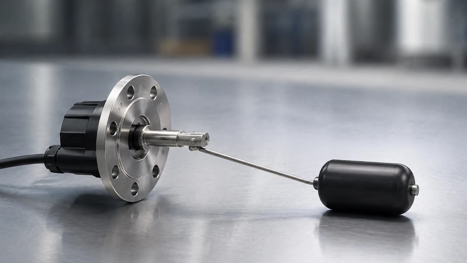
These systems use a float containing a magnet that moves with the fuel level. This float either acts upon an external visual indicator or triggers reed switches at specific heights.
* Advantages: Provides a clear visual reference without requiring power (for the gauge) and is highly durable in rugged industrial environments.
* Suitability: Often used as a secondary redundant system or for simple high/low-level alarms.
Key Evaluation Criteria for Fuel Tank Level Sensors
When evaluating a fuel tank level sensor for a specific project, engineers must look beyond the basic measurement range. The following factors are critical for B2B procurement and system integration:
Media Characteristics
Fuel is not a uniform category. Diesel, gasoline, aviation fuel, and heavy fuel oil (HFO) have different properties. For instance, gasoline is highly volatile and requires explosion-proof (Ex-rated) equipment. Heavy fuel oil may require heating, which necessitates sensors that can withstand high temperatures and potential coating or buildup.
Tank Geometry and Environment
* Tank Height: Small day tanks (1 m to 3 m / 3.2 ft to 9.8 ft) may use ultrasonic or hydrostatic sensors, while large bulk terminals (up to 30 m / 98.4 ft) typically require high-frequency radar.
* Internal Obstructions: If the tank has baffles, agitators, or complex piping, a non-contact sensor with a narrow beam (like 80 GHz radar) is necessary to avoid false echoes.
* Atmospheric Conditions: For tanks located in extreme climates, sensors must have appropriate IP ratings (IP67/IP68) and operating temperature ranges (typically -40°C to +80°C).
Output and Integration
Modern industrial automation requires seamless integration. Most sensors offer 4-20mA analog outputs with HART protocol, while others provide digital communication via RS485 (Modbus RTU) or Profibus. For remote sites, wireless LoRaWAN or NB-IoT integrated sensors are becoming increasingly common for fuel inventory management.
Practical Selection Table
| Technology | Typical Accuracy | Max Range | Best For | Relative Cost |
| :— | :— | :— | :— | :— |
| 80GHz Radar | ±1 mm | 120 m (393 ft) | High-precision bulk storage, volatile fuels | High |
| Ultrasonic | ±0.25% of range | 15 m (49 ft) | Standard diesel tanks, water-oil separators | Medium |
| Hydrostatic | ±0.5% FS | 200 m (656 ft) | Underground tanks, deep wells | Low to Medium |
| Magnetic Float | ±5 mm | 6 m (19.6 ft) | Visual monitoring, high/low alarms | Medium |
For a comprehensive look at specific hardware configurations and technical data sheets, you can Review product options and application support to match a sensor to your specific industrial requirements.
Installation Considerations and Best Practices
Correct installation is as important as the technology itself. Poor placement can lead to signal loss or erratic readings.
1. Avoid the Dead Zone: Every non-contact sensor has a "dead zone" or "blocking distance" (typically 0.1 m to 0.5 m / 0.3 ft to 1.6 ft). Ensure the sensor is mounted high enough that the fuel level never enters this zone, or account for it in the tank calibration.
2. Nozzle Mounting: For radar and ultrasonic sensors, the nozzle height and diameter must be considered. If the nozzle is too narrow or too long, it can create signal interference. The sensor face should ideally protrude slightly into the tank or be flush with the tank roof.
3. Positioning: Do not install the sensor directly above the fuel inlet. The turbulence and bubbles created during filling will cause significant measurement errors and can potentially damage the sensor diaphragm in hydrostatic models.
4. Vertical Alignment: Non-contact sensors must be mounted perfectly perpendicular to the liquid surface. A deviation of just a few degrees can cause the reflected signal to miss the receiver, especially in low-dielectric fuels.
5. Grounding and Shielding: Fuel environments are often prone to static electricity. Ensure all sensors are properly grounded and use shielded cables to prevent EMI (Electromagnetic Interference) from pumps and motors.
Common Risks and Limitations
While modern sensors are highly advanced, certain environmental factors pose risks to accuracy:
* Vapor and Condensation: In high-humidity environments or with volatile fuels, condensation can form on the sensor face. While radar can penetrate some vapor, heavy droplet buildup can attenuate the signal. Some sensors feature a PTFE drip-off design to mitigate this.
* Dielectric Constant ($ε_r$): Radar signals reflect better off materials with high dielectric constants. Fuels typically have low $ε_r$ values (e.g., diesel is ~2.1). If the $ε_r$ is very low, the signal reflection is weak, requiring a more sensitive radar or a guided wave radar (GWR) solution.
* Foaming: During rapid filling, some fuels produce foam. Foam can absorb ultrasonic and radar signals, leading to a "lost echo" condition. In these cases, hydrostatic sensors or GWR are often more reliable as they are less affected by surface foam.
Frequently Asked Questions (FAQs)
Q: Can I use a standard water level sensor for diesel fuel?
A: Not necessarily. You must check material compatibility. Diesel can degrade certain plastics and elastomers used in water sensors. Furthermore, fuel tanks often require ATEX or Class I Div 1 explosion-proof certifications, which standard water sensors may lack.
Q: How often do fuel tank level sensors need calibration?
A: This depends on the technology. Radar and ultrasonic sensors are generally drift-free and may only need a yearly check. Hydrostatic sensors may require more frequent calibration (every 6-12 months) as the diaphragm can age or become fouled by heavy fuel sediments.
Q: What is the best sensor for an underground diesel tank?
A: Hydrostatic pressure transmitters are frequently used due to their ease of installation in narrow access pipes. However, if high precision for leak detection is required, magnetostrictive probes or high-frequency radar are preferred.
Q: How does temperature affect fuel level measurement?
A: Fuel expands and contracts with temperature. A hydrostatic sensor measures mass/pressure, so as the fuel expands (density decreases), the level rises but the pressure stays the same—meaning the sensor might report the same "level" despite a physical height change. Non-contact sensors measure physical height, so they will show the level rise as the fuel warms up. Most B2B fuel management systems use a temperature probe to calculate "net volume" at a standard temperature (e.g., 15°C).
Conclusion
Choosing the right fuel tank level sensor is a balance between technical requirements, environmental constraints, and budget. For critical industrial applications, non-contact radar remains the gold standard for accuracy and low maintenance. However, for simpler monitoring tasks, hydrostatic or ultrasonic solutions provide excellent value.
Before finalizing a specification, project managers should confirm the fuel's chemical properties, the tank's physical dimensions, and the required integration protocols. By following established engineering principles and installation best practices, facilities can ensure accurate fuel inventory, prevent costly overfills, and maintain uninterrupted operations.