Gas Flow Indicator
Gas Flow Indicator
In industrial process engineering, the ability to verify the movement of media within a closed piping system is fundamental to safety and operational efficiency. A gas flow indicator is a mechanical device installed in a pipeline to provide a visual or qualitative confirmation that gas is flowing. While digital flow meters provide quantitative data for control loops, gas flow indicators serve as a primary, often non-electronic, point of verification for operators on the plant floor.
Understanding the nuances of gas flow indication is essential for maintaining systems in water treatment, chemical processing, and industrial automation. This guide explores the principles, selection criteria, and practical application of these instruments in modern industry.
Measurement Principles of Gas Flow Indicators
Gas flow indicators operate on several distinct physical principles, each suited to different gas types, pressures, and visibility requirements. Unlike liquid indicators, gas versions must account for the low density and high compressibility of the media.
Variable Area (Rotameters)
The most common type of gas flow indicator is the variable area meter, or rotameter. It consists of a tapered tube—usually made of glass, plastic, or metal—and an internal float. As gas enters the bottom of the tube, it exerts upward pressure on the float. The float rises until the upward force of the gas flow equals the downward force of gravity. Because the tube is tapered, the gap between the float and the tube wall increases as the float rises, allowing more gas to pass. The position of the float against a calibrated scale provides a direct indication of the flow rate.
Flapper and Paddle Indicators
For applications where a simple "yes/no" flow confirmation is required rather than a precise rate, flapper indicators are used. These devices feature a hinged flap or paddle positioned in the flow path. When gas moves through the pipe, it pushes the flapper forward. The angle of the flapper typically corresponds to the velocity of the flow. These are particularly useful for opaque gases or systems where the presence of flow is more critical than the exact volume.
Ball and Drip Indicators
In low-flow gas applications, a small ball inside a dome or a sight glass may be used. The gas flow causes the ball to dance or hover within the chamber. This provides a highly visible signal even from a distance. Drip indicators are less common for pure gas but are frequently used in gas lines where moisture or condensate may be present, allowing operators to see liquid accumulation.
Sight Flow Indicators
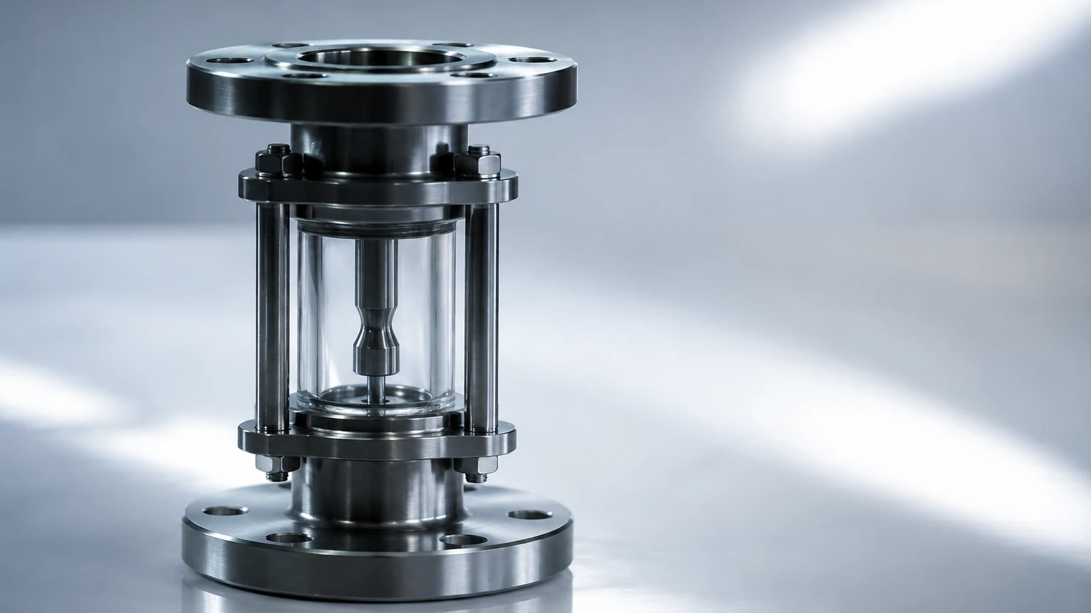
These are essentially windows into the pipeline. A sight flow indicator may not have any moving internal parts, relying instead on the visual turbulence of the gas or the movement of entrained particles. In high-purity gas systems, these are used to ensure the gas remains clear and free of visible contaminants.
Key Evaluation Criteria for Selection
Selecting the correct gas flow indicator requires a thorough analysis of the process conditions. Failure to match the instrument to the environment can lead to glass breakage, seal failure, or inaccurate readings.
1. Pressure and Temperature Ratings
Gas density changes significantly with pressure and temperature. Indicators must be rated for the maximum possible pressure (measured in bar or PSI) and temperature (measured in Celsius or Fahrenheit) of the system. For high-pressure applications, armored rotameters or heavy-duty stainless steel sight glasses are required to prevent catastrophic failure.
2. Material Compatibility
The body, seals, and internal indicators (floats/flappers) must be chemically compatible with the gas.
* Stainless Steel (316L): Preferred for corrosive gases and high-hygiene environments.
* Brass/Bronze: Common for compressed air and inert gases like Nitrogen.
* Borosilicate Glass: Used for sight windows due to its thermal shock resistance and clarity.
* PTFE/Viton: Standard materials for O-rings and seals to ensure leak-proof performance.
3. Flow Range and Scale
Indicators are sized based on the expected flow range, often measured in Normal Liters per Minute (Nl/min) or Standard Cubic Feet per Minute (SCFM). It is critical to specify the "Normal" or "Standard" conditions (typically 0°C and 1.013 bar) because gas volume fluctuates with environmental changes.
4. Visibility and Orientation
Operators must be able to see the indicator clearly. If the pipeline is located in a dark area, indicators with high-contrast floats or integrated lighting are necessary. Furthermore, the orientation of the pipe (horizontal vs. vertical) dictates the type of indicator; for example, standard rotameters must be installed vertically with an upward flow direction.
Comparison of Gas Flow Indicator Types
| Indicator Type | Best Application | Flow Direction | Relative Pressure Drop | Visibility |
| :— | :— | :— | :— | :— |
| Rotameter | Precise flow monitoring | Vertical (Up) | Low to Medium | High (Scale) |
| Flapper | Flow/No-flow detection | Horizontal/Vertical | Moderate | Medium |
| Ball Style | Low-flow verification | Any (with spring) | Low | High |
| Sight Glass | Visual purity check | Any | Negligible | High |
Installation and Maintenance Considerations
Proper installation is the most significant factor in the longevity of a gas flow indicator. Because gases are compressible, turbulence can cause "float bounce" or erratic flapper movement, which leads to premature wear of internal components.
Piping Layout
To ensure a steady flow profile, it is recommended to have at least five to ten diameters of straight pipe upstream of the indicator and three to five diameters downstream. This minimizes turbulence caused by elbows, valves, or reducers. If the gas contains moisture, the indicator should be installed at a high point in the piping to prevent liquid from pooling in the sight chamber.
Safety Precautions
In systems carrying hazardous or flammable gases, the indicator should be equipped with a safety shield. If the glass tube or window were to fail, the shield protects personnel from high-pressure gas or shards. Furthermore, in many industrial settings, flow indicators are used in tandem with level measurement technologies. For instance, when monitoring gas-blanketed storage tanks, the gas flow indicator monitors the nitrogen purge while Main Page instruments like radar or ultrasonic level sensors manage the liquid inventory.
Maintenance Routine
* Cleaning: Over time, gas impurities can coat the inside of the sight glass. Regular cleaning with appropriate solvents is necessary to maintain visibility.
* Seal Inspection: O-rings and gaskets should be inspected annually for signs of brittleness or cracking, especially in outdoor installations exposed to UV light.
* Float Inspection: In rotameters, ensure the float moves freely. Any sticking indicates the presence of oils or particulates in the gas stream.
Common Risks and Limitations
While gas flow indicators are robust, they have specific limitations that engineers must account for during the design phase:
1. Pressure Drop: Every mechanical indicator introduces some resistance to flow. In low-pressure systems, this pressure drop (Delta P) must be calculated to ensure it does not starve downstream equipment.
2. Backflow: Most standard indicators do not act as check valves. If the process experiences backflow, the indicator may be damaged or provide a misleading reading unless a dedicated check valve is installed.
3. Condensation: If a gas stream cools below its dew point, liquid droplets will form. This can cloud the sight glass or cause a mechanical float to stick due to surface tension.
4. Glass Fragility: Despite the use of tempered borosilicate glass, these components remain the weakest link in a metal piping system. They are susceptible to mechanical impact and extreme thermal cycling.
Information to Confirm Before Selection
Before purchasing or specifying a gas flow indicator, project managers and engineers should confirm the following data points:
* Gas Composition: Is the gas dry, wet, corrosive, or flammable?
* Operating Pressure: What is the normal operating pressure and the maximum surge pressure?
* Flow Velocity: What are the minimum and maximum expected flow rates?
* Line Size: What is the exact pipe diameter and connection type (NPT, BSP, or Flanged)?
* Environmental Conditions: Will the unit be installed indoors, outdoors, or in a coastal environment with high salinity?
Frequently Asked Questions (FAQs)
Q: Can a gas flow indicator be used for liquids?
A: Generally, no. Indicators are calibrated based on the density and viscosity of the specific media. A float designed for gas will likely behave differently in a liquid, leading to inaccurate readings or mechanical failure.
Q: What is the difference between a flow indicator and a flow switch?
A: A flow indicator provides a visual reference for the operator. A flow switch includes an electrical contact (like a reed switch) that sends a signal to a control system when flow reaches a certain threshold. Many modern indicators can be retrofitted with switch kits.
Q: How do I prevent the sight glass from fogging?
A: In applications where temperature differentials cause fogging, double-window indicators or units with internal heaters can be used. Alternatively, ensuring the gas is properly dried upstream will eliminate the source of the moisture.
Q: Are there digital versions of these indicators?
A: Yes, some units feature a mechanical primary indicator with a digital secondary display. However, for many B2B applications, the reliability of a purely mechanical Main Page style indicator is preferred as it functions during power outages.
In summary, the gas flow indicator is an indispensable tool for local process verification. By selecting the appropriate measurement principle and ensuring compatible materials, industrial facilities can maintain high safety standards and operational clarity. For comprehensive process monitoring, these devices should be integrated into a broader strategy that includes precise level and pressure measurement to ensure the total integrity of the fluid handling system.