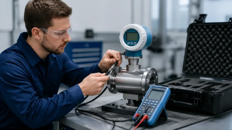
Gas Flow Meters Signal/power Solutions
Gas Flow Meters Signal/power Solutions
In industrial process control, the accuracy of gas flow measurement is as critical as the reliability of the infrastructure supporting it. Gas flow meters signal/power solutions represent the backbone of data acquisition and instrument operation in environments ranging from clean laboratory settings to harsh, explosive oil and gas fields. Selecting the correct power supply and signal transmission method is not merely a matter of electrical compatibility; it is a fundamental engineering decision that affects measurement precision, system safety, and long-term maintenance costs.
Industrial gas flow meters, much like the advanced instrumentation found on the Main Page of professional equipment providers, must operate within strict electrical parameters to ensure that the data reaching the PLC (Programmable Logic Controller) or SCADA system is a true reflection of the process conditions. This article explores the technical principles, selection criteria, and practical implementation of signal and power configurations for modern gas flow measurement.
Measurement Principles and Signal Generation
Before addressing the power and signal infrastructure, it is essential to understand how different gas flow meters generate their primary signals. The method of transduction dictates the power requirements and the type of signal output available.
Thermal Mass Flow Meters
Thermal mass flow meters operate on the principle of thermal diffusion. They typically use two RTD (Resistance Temperature Detector) sensors: one as a velocity sensor and one as a temperature sensor to compensate for gas temperature changes. The power solution must be robust enough to provide a constant heating current to the velocity sensor. Because this heating element consumes significant energy, these meters often require higher power budgets than simple pressure-based instruments.
Vortex Shedding Flow Meters
Vortex meters utilize a bluff body placed in the flow stream to create vortices. A piezoelectric sensor detects the frequency of these vortices, which is linearly proportional to the gas velocity. The signal generated is essentially a frequency pulse, which can be converted into a 4-20mA analog signal or a digital protocol. These units are often available in low-power, loop-powered configurations.
Ultrasonic Gas Flow Meters
Ultrasonic meters measure the time difference between pulses traveling with and against the flow. These instruments require sophisticated digital signal processing (DSP) to calculate the flow rate accurately. Consequently, their power solutions must support high-speed electronic components, often necessitating a 4-wire configuration for optimal performance.
Power Solutions for Gas Flow Meters
The choice of power supply is often dictated by the installation site's infrastructure and the instrument's energy consumption. In industrial automation, three primary power configurations dominate the landscape.
1. 2-Wire (Loop-Powered) Systems
In a 2-wire configuration, the signal and power share the same pair of wires. The instrument receives its power from the 24V DC loop and modulates the current between 4mA and 20mA to represent the flow rate.
- Advantages: Reduced cabling costs, simplified installation, and inherent suitability for Intrinsically Safe (IS) circuits.
- Limitations: Limited power budget (usually less than 35mW available for the electronics), which may not support advanced features like high-contrast backlit displays or intensive heating elements in thermal meters.
2. 3-Wire and 4-Wire Systems
These systems separate the power supply from the signal output. A 4-wire system uses two wires for power (AC or DC) and two wires for the signal output.
- Advantages: Provides ample power for high-accuracy electronics, large displays, and communication modules. Ideal for ultrasonic and high-performance thermal mass meters.
- Limitations: Higher installation costs due to additional cabling and the need for separate power distribution units.
3. Battery and Solar Solutions
For remote gas pipelines or wellhead monitoring where grid power is unavailable, battery-powered gas flow meters are essential. These units are designed for ultra-low power consumption, often remaining in a "sleep" mode and waking up at intervals to take a measurement.
- Considerations: Battery life is highly dependent on the sampling frequency and the use of wireless transmission (e.g., NB-IoT or LoRaWAN).
Signal Transmission Solutions
Once the gas flow is measured and the instrument is powered, the data must be transmitted to the control room. Modern gas flow meters signal/power solutions offer several layers of data communication.
Analog Signals (4-20mA)
The 4-20mA current loop remains the industry standard due to its robustness against electrical noise and its ability to travel over long distances (up to 1,000 meters) without significant signal degradation. However, it only carries a single variable (e.g., instantaneous flow rate).
Digital Protocols (HART, Modbus, Profibus)
To extract more data—such as totalized flow, gas temperature, and diagnostic alerts—digital protocols are used:
- HART: Superimposes a digital signal on top of the 4-20mA analog loop. It is widely used for instrument configuration and diagnostics.
- Modbus RTU (RS485): A multi-drop protocol that allows several meters to be daisy-chained on a single cable, significantly reducing wiring complexity in large-scale installations.
Wireless Signal Solutions
Wireless transmission is increasingly common for non-critical monitoring. By using cellular (LTE-M/NB-IoT) or radio (LoRa) signals, operators can monitor gas flow in remote locations without the massive capital expenditure of trenching and cabling.
Selection Table: Signal and Power Configurations
| Meter Type | Typical Power | Primary Signal | Best Application |
| :— | :— | :— | :— |
| Thermal Mass | 24V DC (4-wire) | 4-20mA / Modbus | Compressed air, process gas monitoring |
| Vortex | 24V DC (2-wire) | 4-20mA / HART | Steam, high-velocity gas flow |
| Ultrasonic | 24V DC / AC | Modbus / Ethernet | Custody transfer, large diameter pipes |
| Turbine | Battery / 2-wire | Pulse / 4-20mA | Natural gas distribution, low-viscosity gas |
Installation and Safety Considerations
When implementing gas flow meters signal/power solutions, engineering teams must adhere to strict installation guidelines to ensure accuracy and safety, particularly in hazardous areas.
1. Hazardous Area Classification: Gas flow measurement often involves flammable media. Instruments must be rated for the specific zone (e.g., ATEX Zone 0, 1, or 2). Intrinsically Safe (IS) barriers are required for 2-wire loops in Zone 0/1 to prevent electrical sparks.
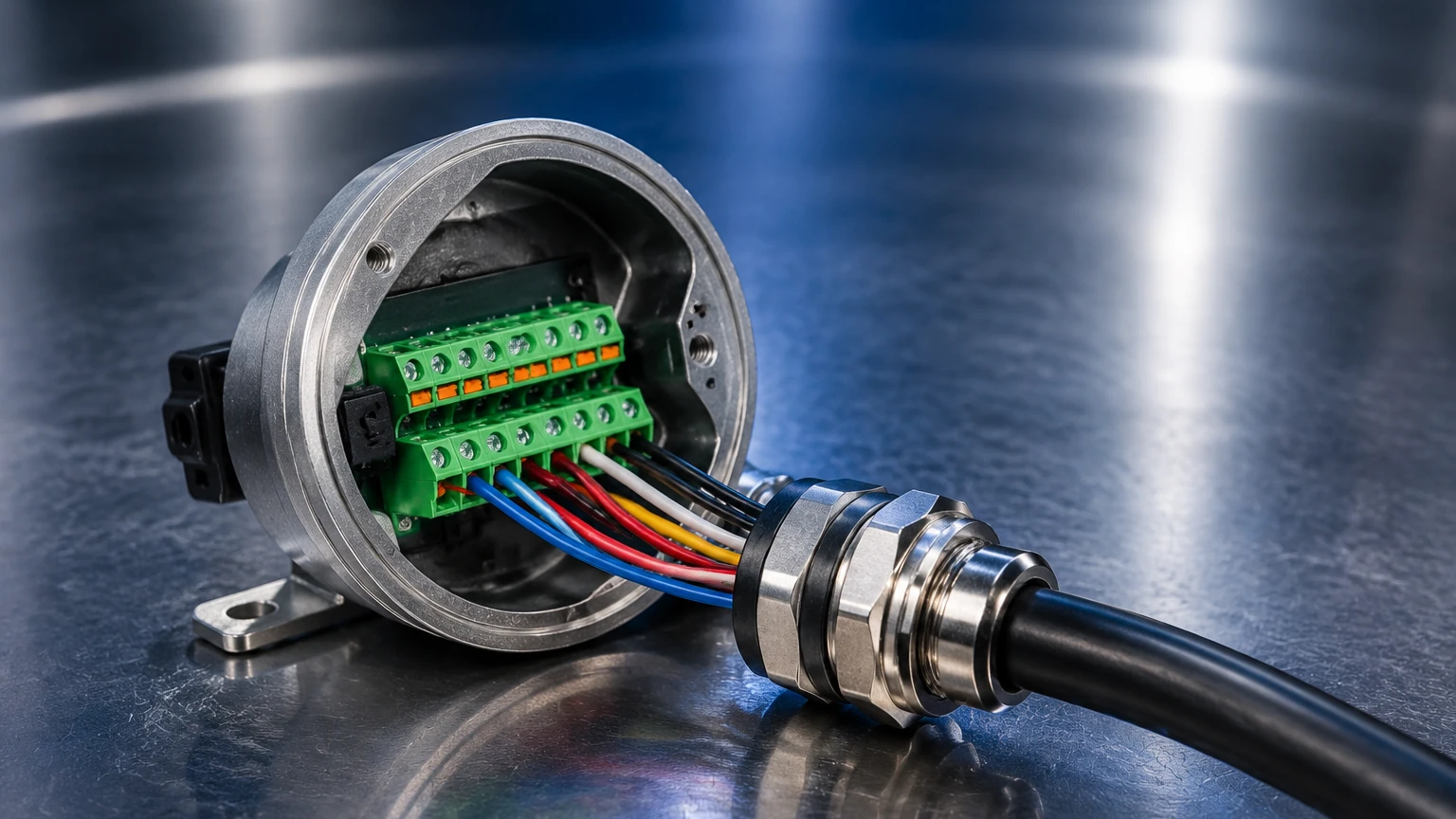
2. Cable Shielding: To prevent electromagnetic interference (EMI) from variable frequency drives (VFDs) or high-voltage lines, shielded twisted-pair cables should be used for all signal transmissions. The shield should be grounded at only one end (usually the control room) to avoid ground loops.
3. Voltage Drop Calculations: For long cable runs, engineers must calculate the voltage drop to ensure that the instrument receives at least its minimum required operating voltage (typically 12V to 15V DC at the terminals for a 24V loop).
4. Grounding: Proper earthing of the meter body is essential, especially for meters using piezoelectric sensors or high-frequency electronics, to ensure a stable reference point for the signal.
Limitations and Challenges
While modern solutions are highly advanced, certain limitations persist:
- Signal Distance: Analog signals can suffer from voltage drops over extreme distances, while RS485 digital signals may require repeaters beyond 1,200 meters.
- Power Consumption: High-accuracy meters with complex DSP or heating elements cannot be powered by standard 2-wire loops, necessitating more expensive 4-wire installations.
- Environmental Interference: High-humidity or corrosive environments can degrade terminal connections, leading to signal drift or intermittent power loss. Using high-quality, IP67-rated enclosures and gold-plated connectors can mitigate these risks.
Frequently Asked Questions (FAQs)
Q: Can I use a 2-wire gas flow meter in an explosion-proof application?
A: Yes, but it requires an Intrinsically Safe (IS) barrier located in the safe area to limit the energy entering the hazardous zone. Alternatively, the meter can be housed in an explosion-proof (Ex d) enclosure.
Q: What is the benefit of using Modbus over 4-20mA for gas flow?
A: Modbus allows you to read multiple parameters (flow rate, temperature, pressure, and totalizer) over a single pair of wires, whereas 4-20mA only provides one parameter. Modbus also provides digital accuracy without the A/D conversion errors associated with analog loops.
Q: How do I handle signal interference in a plant with many large motors?
A: Use shielded twisted-pair (STP) cabling, ensure proper grounding, and maintain physical separation between signal cables and high-power electrical conduits. Digital signals like HART or Modbus are generally more resilient to noise than raw analog pulses.
Q: Is solar power viable for gas flow meters?
A: Yes, provided the meter is designed for low power consumption. It is common to use a solar panel to charge a lead-acid or lithium battery, which then powers the meter and a wireless transmitter.
For engineers seeking comprehensive measurement hardware and technical support, reviewing the various product options and application support available on the Main Page can provide further insights into integrating these flow solutions with existing level and pressure monitoring systems. Proper alignment of power and signal infrastructure ensures that the gas flow meter remains a reliable asset throughout its operational lifecycle.