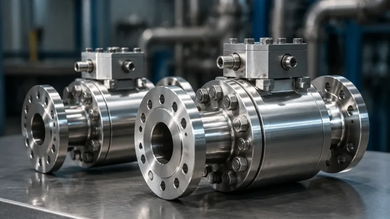
Ge Flow Meter
Ge Flow Meter
In the landscape of industrial automation and process control, the accurate measurement of fluid movement is as critical as the monitoring of static volumes. For engineers and procurement specialists, the search for a "ge flow meter" often leads to the realm of high-precision ultrasonic and vortex technologies. General Electric (GE), through its legacy brands like Panametrics, established a gold standard for non-invasive flow measurement. Understanding the principles behind these instruments, their selection criteria, and how they interface with level measurement systems is essential for optimizing plant efficiency and safety.
This guide examines the technical foundations of flow measurement, specifically focusing on the ultrasonic technologies often associated with the ge flow meter category, and provides a comparative framework for selecting the right instrumentation for liquid and gas applications.
Measurement Principles: Ultrasonic Flow Technology
Most modern flow meters categorized under the GE or Panametrics lineage utilize ultrasonic waves. Unlike mechanical flow meters that rely on moving parts, ultrasonic meters use sound propagation to determine velocity. There are two primary methods: Transit-Time and Doppler.
Transit-Time Ultrasonic Principle
Transit-time measurement is the most common principle used in high-end industrial flow meters. It relies on the fact that sound waves traveling with the flow of a fluid move faster than those traveling against it.
The meter utilizes pairs of transducers, each acting as both a transmitter and a receiver. One transducer sends a signal downstream, while the other sends a signal upstream. The time difference (Δt) between these two signals is directly proportional to the velocity of the fluid.
The formula for velocity (V) is generally expressed as:
V = (L / 2cosθ) × (Δt / (t_up × t_down))
Where:
* L is the distance between transducers.
* θ is the angle of the ultrasonic path relative to the flow.
* t_up is the time for the signal to travel upstream.
* t_down is the time for the signal to travel downstream.
This method is highly accurate for clean liquids and gases where the Reynolds number is well-defined. It is the preferred technology for custody transfer and high-precision process monitoring.
Doppler Ultrasonic Principle
In contrast, Doppler flow meters are used for "dirty" liquids—those containing entrained bubbles or suspended solids. The transducers emit a steady frequency into the fluid. These sound waves reflect off the particles or bubbles. Because the particles are moving, the reflected frequency shifts (the Doppler Effect). The frequency shift is proportional to the flow velocity. While generally less accurate than transit-time meters, Doppler meters are indispensable in wastewater treatment and mining slurries where other sensors would fail.
The Relationship Between Flow and Level Measurement
While a ge flow meter typically measures velocity within a closed pipe, many industrial applications require flow measurement in open channels, such as flumes, weirs, or partially filled pipes. In these scenarios, flow measurement is actually a derivative of level measurement.
Using ultrasonic or radar level sensors, such as those provided on our Main Page, operators measure the head (height) of the liquid at a specific point in a flume. By applying the Manning equation or specific discharge curves for a weir, the level is converted into a volumetric flow rate (m³/h or liters per second).
| Application Type | Primary Instrument | Measurement Principle |
| :— | :— | :— |
| Closed Pipe (Clean) | Transit-Time Flow Meter | Sound Velocity Differential |
| Closed Pipe (Slurry) | Doppler Flow Meter | Frequency Shift |
| Open Channel/Flume | Ultrasonic Level Sensor | Time-of-Flight (Level-to-Flow) |
| High-Pressure Steam | Vortex Flow Meter | Karman Vortex Shedding |
Key Evaluation Criteria for Selection
When specifying a flow meter, whether looking for a ge flow meter or a compatible alternative, several technical factors must be confirmed to ensure long-term reliability.
1. Fluid Characteristics
* Phase: Is the medium liquid, gas, or steam?
* Viscosity: High-viscosity fluids (e.g., heavy oils) may require specific transducer configurations to overcome signal attenuation.
* Conductivity: Unlike electromagnetic flow meters, ultrasonic meters do not require the fluid to be conductive, making them ideal for deionized water and hydrocarbons.
* Temperature and Pressure: Standard transducers often operate up to 150°C (302°F), but specialized high-temperature buffers are required for steam or molten processes.
2. Pipe Specifications
* Material: Carbon steel, stainless steel, and plastic are ideal. Liners (like Teflon or rubber) must be well-bonded to the pipe wall to prevent air gaps that block ultrasonic signals.
* Diameter: Flow meters are available for ranges from 12.7 mm (0.5 inches) to over 5000 mm (200 inches).
* Condition: Internal scaling or heavy corrosion can interfere with signal propagation, necessitating the use of wetted transducers rather than clamp-on models.
0
3. Accuracy and Rangeability (Turndown Ratio)
Industrial-grade ultrasonic meters typically offer accuracies of ±0.5% to ±1% of reading. The turndown ratio—the ratio of maximum to minimum measurable flow—is often as high as 400:1, far exceeding the 10:1 ratio common in traditional orifice plates.
Practical Selection Table for Industrial Flow Meters
| Feature | Transit-Time (Clamp-on) | Transit-Time (Wetted) | Vortex Flow Meter |
| :— | :— | :— | :— |
| Installation | Non-invasive (No shutdown) | Inline (Requires shutdown) | Inline |
| Maintenance | Very Low | Low | Moderate |
| Accuracy | ±1.0% to ±2.0% | ±0.5% | ±1.0% |
| Fluid Type | Clean Liquids/Gases | Clean Liquids/Gases | Steam/Gas/Liquids |
| Pipe Size | 12.7 mm to 5000 mm | 50 mm to 600 mm | 15 mm to 300 mm |
| Pressure Drop | Zero | Negligible | Moderate |
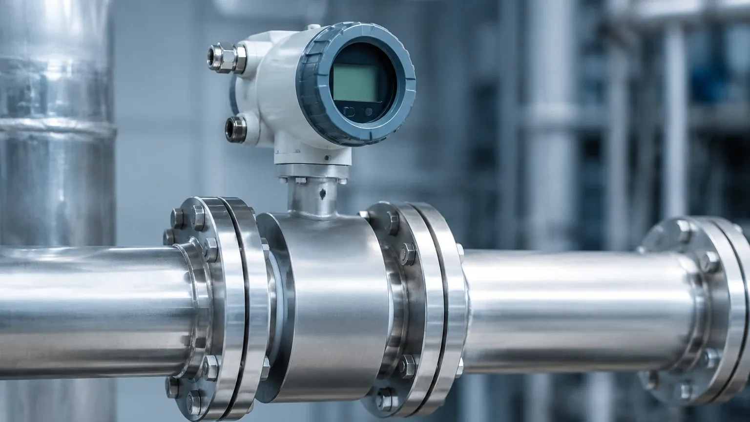
Installation Considerations and Best Practices
Even the most advanced ge flow meter will fail to provide accurate data if installed incorrectly. The following engineering guidelines should be strictly followed:
Straight Pipe Run Requirements
Flow meters require a developed flow profile to measure accurately. Turbulence caused by elbows, valves, or pumps can create significant errors.
* Upstream: Minimum 10D (10 times the pipe diameter) of straight, unobstructed pipe.
* Downstream: Minimum 5D of straight pipe.
* If a pump is located upstream, the requirement may increase to 30D or more.
Transducer Orientation
For horizontal pipes, transducers should never be mounted at the very top or bottom of the pipe.
* Top Mounting: Risk of air bubbles collecting at the top, which block the signal.
* Bottom Mounting: Risk of sediment or solids settling at the bottom, which attenuate the signal.
* Recommended: Mount at the 3 o'clock or 9 o'clock positions (the sides).
Coupling Compounds
For clamp-on ultrasonic meters, the interface between the transducer and the pipe wall must be filled with a coupling grease or gel. This eliminates the air gap. In permanent installations, solid epoxy or stainless steel foils are used to ensure the coupling does not degrade over time due to evaporation or heat.
Common Risks and Limitations
While ultrasonic flow measurement is highly versatile, it is not a universal solution. Engineers must be aware of the following limitations:
1. Aeration and Cavitation: If a liquid contains more than 2% to 5% bubbles by volume, transit-time signals will be scattered, leading to a "signal loss" error. This often happens downstream of control valves or in suction lines.
2. Pipe Wall Interference: Very old cast iron pipes or pipes with significant internal pitting may not allow the ultrasonic signal to pass through cleanly. In these cases, a wetted (inline) sensor is mandatory.
3. Low Flow Cut-off: Most digital flow meters have a programmable low-flow cut-off. If the velocity drops below a certain threshold (e.g., 0.03 m/s), the meter will read zero to prevent "ghost" readings caused by thermal convection or vibration.
Frequently Asked Questions (FAQ)
Q: Can a ge flow meter measure steam?
A: Yes, specific vortex and ultrasonic models are designed for saturated and superheated steam. However, they require specialized transducers and pressure/temperature compensation to calculate mass flow accurately.
Q: What is the difference between a flow meter and a flow switch?
A: A flow meter provides a continuous measurement of the rate (e.g., m³/h), whereas a flow switch only indicates whether the flow is above or below a specific setpoint (on/off signal).
Q: How often should an ultrasonic flow meter be calibrated?
A: For non-critical process monitoring, every 2-3 years is standard. For custody transfer or regulated environmental reporting, annual calibration is typically required. Since clamp-on meters have no moving parts, their electronic calibration is very stable, but the physical coupling should be inspected annually.
Conclusion: Selecting the Right Solution
Whether you are integrating a ge flow meter into a complex chemical process or looking for a cost-effective level-based flow solution for water treatment, the key lies in understanding the physics of your medium. Flow and level measurement are two sides of the same coin in industrial automation; often, the most robust system utilizes both to provide a complete picture of process health.
For those managing bulk storage or processing tanks, ensuring that your flow data aligns with your level inventory is the best way to detect leaks and optimize throughput. To explore high-precision level instruments that complement your flow measurement strategy, visit our Main Page for technical specifications and application support. Accurate measurement starts with selecting the right technology for the specific challenges of your operating environment.