Grain Silo Level Sensor
Grain Silo Level Sensor
In the agricultural and food processing industries, the grain silo level sensor is a critical component for inventory management, process efficiency, and safety. Monitoring the volume of bulk solids such as corn, wheat, soybeans, and rice presents unique engineering challenges. Unlike liquids, grains create uneven surfaces, generate significant amounts of dust, and have varying dielectric properties that can interfere with signal accuracy.
Selecting the correct instrumentation requires an understanding of how different technologies interact with the physical properties of the grain and the silo environment. This guide examines the primary measurement principles, selection criteria, and installation best practices for industrial grain level monitoring. For a broader look at industrial measurement options, engineers often refer to the Main Page of instrumentation providers to compare sensor specifications.
Measurement Principles for Grain Silos
To choose the right grain silo level sensor, it is essential to understand the physics behind the most common measurement methods. These technologies generally fall into two categories: continuous level measurement and point level detection.
Non-Contact Radar (FMCW)
Radar sensors are the gold standard for grain silos. High-frequency radar, particularly those operating at 80 GHz, uses Frequency Modulated Continuous Wave (FMCW) technology. The sensor emits a continuous signal with a changing frequency. The signal reflects off the grain surface and returns to the sensor. By measuring the frequency difference between the emitted and received signals, the device calculates the distance with high precision.
* Advantages: 80 GHz radar has a narrow beam angle (often as small as 3 degrees), which allows it to avoid internal silo structures like ladders or braces. It is largely unaffected by the heavy dust clouds generated during filling.
* Limitations: Extremely low dielectric constants (εr < 1.4) can occasionally result in weak signal returns, though most grains fall within a measurable range (εr 2.0 to 5.0).
Ultrasonic Level Sensors
Ultrasonic sensors work on the Time-of-Flight (ToF) principle. The sensor sends an acoustic pulse that travels through the air, bounces off the grain, and returns. The distance is calculated based on the speed of sound.
* Advantages: Cost-effective for smaller silos and non-hazardous environments.
* Limitations: Sound waves are easily scattered by the uneven surface of grain (the angle of repose). More importantly, the thick dust common in grain silos can absorb the acoustic energy, leading to signal loss. They are generally not recommended for large-scale industrial grain storage.
Guided Wave Radar (GWR)
GWR uses a probe (usually a steel cable) that extends to the bottom of the silo. A low-energy microwave pulse travels down the cable. When it hits the grain, the change in dielectric constant causes a reflection.
* Advantages: Provides a very stable signal and is unaffected by dust or air turbulence.
* Limitations: The main risk is the high tensile load exerted on the cable by the downward movement of the grain during discharge. In tall silos, this force can exceed several tons, potentially damaging the sensor or the silo roof.
Rotary Paddle Switches (Point Level)
These are used for high-level or low-level alarms rather than continuous measurement. A small motor rotates a paddle. When the grain reaches the paddle, it creates resistance, stopping the motor and triggering a switch.
Practical Selection Table
The following table compares the most common technologies used for grain silo level measurement to assist in the initial engineering phase.
| Technology | Accuracy | Max Range | Dust Resistance | Mounting Complexity | Typical Application |
| :— | :— | :— | :— | :— | :— |
| 80 GHz Radar | ±1 mm to ±3 mm | 120 m (393 ft) | Excellent | Low | Large concrete or steel silos |
| 26 GHz Radar | ±5 mm | 30 m to 70 m | Good | Medium | Medium-sized bins |
| Guided Wave Radar | ±5 mm | 30 m (98 ft) | Excellent | High (Tensile Load) | Low-dielectric powders |
| Ultrasonic | ±0.25% of range | 15 m (49 ft) | Poor | Low | Small hoppers, low dust |
| Rotary Paddle | N/A (Point) | N/A | Excellent | Low | Overfill protection |
Key Selection Criteria for Grain Silos
When specifying a grain silo level sensor, several environmental and material factors must be evaluated to ensure long-term reliability.
1. Dust and Vapor
Grain handling is inherently dusty. During the filling process, dust concentrations can become so high that they attenuate acoustic signals (ultrasonic) or lower-frequency radar signals (6 GHz or 26 GHz). 80 GHz radar is preferred because its shorter wavelength penetrates dust more effectively and the narrow beam minimizes reflections from the dust cloud itself.
2. Angle of Repose and Surface Profile
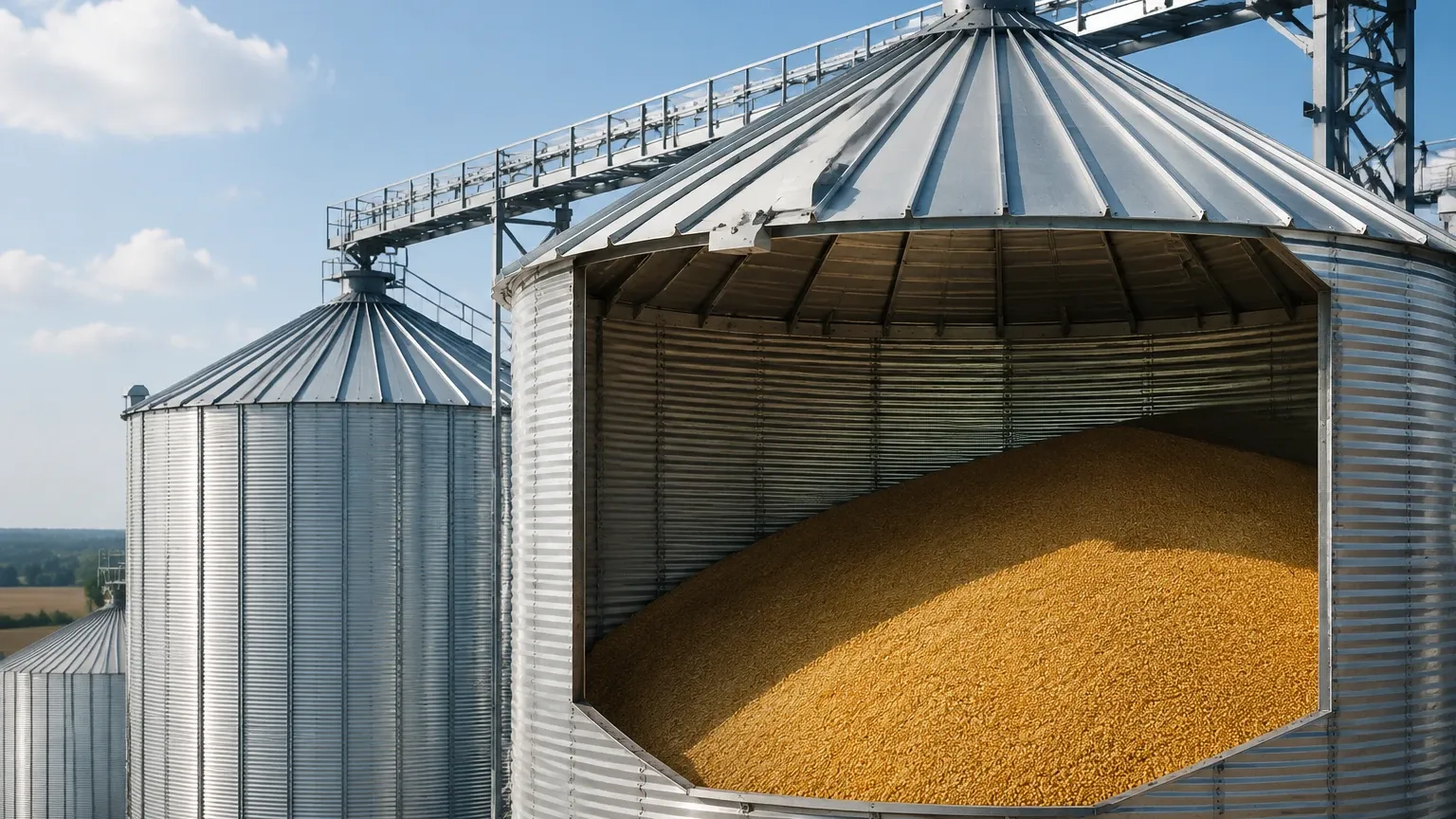
Grains do not sit flat; they form a cone when filled and an inverted cone when emptied. This "angle of repose" means a single-point sensor might report different volumes depending on where it is mounted. For high-accuracy inventory, sensors with "multi-point" mapping or specific aiming flanges are used to account for the uneven surface.
3. Dielectric Constant (εr)
The dielectric constant of the grain determines how much energy is reflected back to the sensor. Most grains have a dielectric constant between 2 and 5. If the grain is very dry, the εr is lower, making it harder for the sensor to "see" the surface. Radar sensors must be sensitive enough to detect these weak reflections.
4. Silo Geometry and Internal Obstructions
Many grain silos contain internal stiffeners, temperature cables, and ladders. A sensor with a wide beam angle will hit these obstructions, creating "false echoes." Using a sensor with a narrow beam (3° to 4°) ensures the signal reaches the grain surface without interference.
Installation and Engineering Best Practices
Proper installation is as important as selecting the right technology. Incorrect placement can lead to erratic readings or premature sensor failure.
Mounting Location
As a general rule, the sensor should not be mounted in the center of the silo or too close to the wall.
* Avoid the Fill Stream: Never mount a sensor directly over the grain inlet. The falling grain will block the signal and may damage the sensor over time.
* The 1/6th Rule: For flat-bottom silos, mounting the sensor at approximately 1/6th to 1/3rd of the diameter from the side wall often provides the most representative average level of the cone.
Aiming and Flanges
Because of the angle of repose, the radar signal may reflect away from the sensor head rather than back toward it. Using an adjustable aiming flange (swivel holder) allows engineers to tilt the sensor toward the middle of the grain slope, maximizing the returned signal strength.
Tensile Load Considerations (For GWR)
If using Guided Wave Radar, the silo roof must be reinforced. As grain settles and is discharged, it pulls down on the cable with immense force. Engineers must calculate the "pull-down force" based on the silo height and grain density to ensure the sensor's process connection and the silo's structural integrity can handle the load.
Explosion Hazards
Grain dust is highly combustible. All sensors installed in grain silos must carry appropriate hazardous area certifications, such as ATEX or IECEx (Zone 20, 21, or 22), to prevent the instrument from becoming an ignition source.
Limitations and Operational Risks
While modern sensors are highly advanced, they are not without limitations.
* Signal Attenuation: In extremely tall silos (over 60 meters), even radar can struggle if the grain is very fine and the dust is exceptionally dense. In these cases, high-power emitters are required.
* Condensation: In silos located in humid environments or areas with large temperature swings, condensation can form on the sensor face. While radar can see through a thin film of water, heavy droplets can cause signal scattering. Sensors with PTFE (Teflon) faces or air purge connections are used to keep the antenna clean.
* Mechanical Wear: In abrasive grain environments, contact-based sensors (like GWR cables) will eventually wear out and need replacement. Non-contact radar is generally preferred to reduce maintenance costs.
Frequently Asked Questions (FAQs)
Q: Can a grain silo level sensor measure volume accurately?
A: A level sensor measures distance. To calculate volume, the silo's dimensions and the grain's bulk density must be programmed into the controller or PLC. Because of the angle of repose, the volume calculation is always an estimate unless a 3D solids scanner is used.
Q: How does moisture content affect the measurement?
A: Moisture increases the dielectric constant of the grain. This actually makes the grain easier for radar to detect, as the reflection becomes stronger. However, if the moisture causes the grain to clump or stick to the sensor, it can cause false high readings.
Q: Is maintenance required for non-contact radar sensors?
A: Generally, very little. If the silo is extremely dusty, an occasional check to ensure the antenna face isn't caked with material is recommended. Many high-end sensors feature a self-cleaning air purge system to automate this.
Q: Why use 80 GHz radar instead of 26 GHz?
A: 80 GHz radar offers a narrower beam and better focus. This makes it easier to install in silos with internal obstructions and provides a more reliable signal when dealing with the complex reflections of a grain surface.
For technical specifications and to explore various sensor models suitable for agricultural applications, visiting the Main Page of a specialized manufacturer can provide the necessary data sheets and application support for specific project requirements.