Heat Transfer Fluids Flow Meter
Heat Transfer Fluids Flow Meter
In industrial process heating and cooling, the efficient movement of thermal energy is fundamental to production quality and operational safety. Heat transfer fluids (HTFs), ranging from water and glycols to specialized synthetic oils, are the primary vehicles for this energy. However, managing these fluids requires precise instrumentation. A heat transfer fluids flow meter is a critical component in these systems, ensuring that the correct volume or mass of fluid is circulating to maintain stable process temperatures.
Accurate flow measurement allows for optimized pump performance, leak detection, and precise heat balance calculations. This guide examines the technical principles, selection criteria, and installation requirements for flow meters used in high-temperature thermal fluid applications.
Understanding Heat Transfer Fluids and Their Challenges
Heat transfer fluids are designed to transport thermal energy between a heat source (such as a boiler or heater) and a heat sink (the process equipment). Unlike water, which has a limited temperature range and high vapor pressure, specialized HTFs can operate at temperatures exceeding 300°C (572°F) while remaining in a liquid state at relatively low pressures.
Fluid Characteristics
Industrial HTFs generally fall into three categories:
1. Water and Glycol Mixtures: Typically used for low to medium temperature ranges (-40°C to 150°C). They offer high specific heat but are limited by boiling points.
2. Mineral Oils: Derived from petroleum, these are cost-effective for temperatures up to 280°C.
3. Synthetic Fluids: Chemically engineered fluids (such as aromatics or silicone-based oils) capable of operating from -90°C to over 400°C.
The Impact of Temperature on Measurement
The primary challenge in HTF flow measurement is the significant change in fluid properties as temperature fluctuates. As an HTF heats up, its density decreases and its kinematic viscosity drops. For example, a synthetic oil might have a viscosity of 500 cSt at startup (20°C) but drop to less than 1 cSt at operating temperature (300°C). A flow meter must be capable of handling these wide ranges without losing accuracy or suffering mechanical failure.
Core Measurement Principles for HTF Flow
Selecting the right heat transfer fluids flow meter requires an understanding of the underlying physics of different measurement technologies. No single technology is universal; each has trade-offs regarding temperature limits, pressure drop, and maintenance requirements.
1. Vortex Shedding Flow Meters
Vortex meters operate on the Karman Vortex Street principle. When a fluid flows past a bluff body (a non-streamlined object) placed in the flow stream, it creates alternating vortices. The frequency of these vortices is directly proportional to the flow velocity.
* Advantages: Vortex meters have no moving parts, making them highly durable in high-temperature HTF loops. They are naturally suited for high-velocity flows and are relatively independent of fluid density and viscosity changes, provided the Reynolds number remains above a certain threshold (typically >20,000).
* Limitations: They require a minimum flow velocity to "trip" the sensor and generate vortices. At very low flow rates or during cold startups where viscosity is high, the meter may fail to register flow.
2. Differential Pressure (DP) Flow Meters
DP flow measurement is one of the oldest and most understood technologies. It involves placing a primary element, such as an orifice plate, Venturi tube, or Pitot tube, in the pipe to create a pressure drop. The square root of this pressure drop is proportional to the flow rate.
* Advantages: These systems can handle extremely high temperatures because the electronics (the DP transmitter) can be isolated from the hot pipe using impulse lines filled with cooler fluid.
* Limitations: The orifice plate creates a permanent pressure drop, increasing pumping costs. Furthermore, because DP meters measure volumetric flow, they require secondary temperature and pressure compensation to calculate mass flow or energy transfer accurately.
3. Coriolis Mass Flow Meters
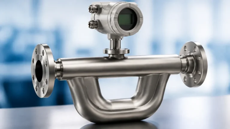
Coriolis meters measure mass flow directly by vibrating a tube (or tubes) through which the fluid flows. The fluid's inertia causes a twist or phase shift in the tube's vibration, which is directly proportional to the mass flow rate.
* Advantages: This is the most accurate technology available (often ±0.1%). Since it measures mass directly, it is unaffected by the density changes common in HTF systems. Most Coriolis meters also provide a high-accuracy density and temperature output.
* Limitations: High-temperature versions are expensive and bulky. The internal tubes must be able to withstand thermal expansion without fatiguing. Pressure drop can also be significant in high-viscosity startup conditions.
4. Ultrasonic Flow Meters (Transit-Time)
Ultrasonic meters use transducers to send sound waves through the fluid. The time difference between waves traveling with the flow and against the flow determines the velocity.
* Advantages: Non-invasive (clamp-on) versions are available, meaning the meter never touches the hot oil. This eliminates leak paths and pressure drops. In-line versions offer high accuracy and a wide turndown ratio.
* Limitations: High-temperature HTFs can exceed the temperature limits of standard ultrasonic transducers. Specialized "wave-guide" mounts are often required to isolate the sensors from the heat. The fluid must also be relatively free of entrained air or solids.
Technical Selection Criteria for Engineers
When evaluating a heat transfer fluids flow meter, engineers must look beyond the basic flow range. The following factors are critical for long-term reliability:
1. Operating vs. Design Temperature: Ensure the meter is rated for the maximum possible excursion temperature, not just the normal operating point. Sensors and gaskets are the most common failure points.
2. Viscosity at Startup: In many HTF systems, the fluid is extremely viscous when the system is cold. The flow meter must be able to withstand the high torque or pressure drop associated with cold starts, even if it doesn't measure accurately until the fluid thins out.
3. Materials of Construction: 316L Stainless Steel is standard, but some HTFs may require specific alloys. Ensure all seals (O-rings or gaskets) are made of high-temperature graphite or specialized fluoropolymers.
4. Turndown Ratio: This is the ratio of maximum to minimum measurable flow. If a process requires precise control at both high and low loads, a high turndown ratio (like that of a Coriolis or Ultrasonic meter) is necessary.
Practical Selection Table
| Feature | Vortex | Coriolis | DP (Orifice) | Ultrasonic (In-line) |
| :— | :— | :— | :— | :— |
| Primary Measurement | Velocity | Mass | Differential Pressure | Velocity |
| Max Temperature | Up to 450°C | Up to 350°C | Up to 500°C+ | Up to 260°C (Standard) |
| Accuracy | ±1.0% of rate | ±0.1% to ±0.2% | ±1.0% to ±3.0% | ±0.5% to ±1.0% |
| Pressure Drop | Low | High | Medium/High | Negligible |
| Moving Parts | None | None (Vibrating) | None | None |
| Typical Turndown | 10:1 to 20:1 | 100:1 | 4:1 | 50:1 |
Installation and Engineering Best Practices
Correct installation is as important as meter selection. High-temperature HTF systems present unique mechanical challenges.
Straight Run Requirements
Most velocity-based meters (Vortex, DP, Ultrasonic) require a specific length of straight pipe upstream and downstream of the sensor to ensure a stable, non-turbulent flow profile. Typically, this is 10 to 20 diameters upstream and 5 diameters downstream. If space is limited, flow conditioners may be required.
Thermal Expansion and Stress
In a system heating from 20°C to 300°C, a 10-meter section of carbon steel pipe will expand by approximately 35mm. Flow meters must be installed in a way that piping stress—caused by this expansion—is not transferred to the meter body. Use expansion loops and proper pipe supports to isolate the instrument.
Insulation Considerations
While the pipe must be insulated for energy efficiency and personnel safety, the electronics housing of the flow meter (the transmitter) must remain cool. Most high-temperature meters use an "extension neck" to move the electronics away from the hot pipe. Never wrap insulation around the transmitter or the cooling fins of the extension neck, as this will lead to electronic component failure.
Orientation
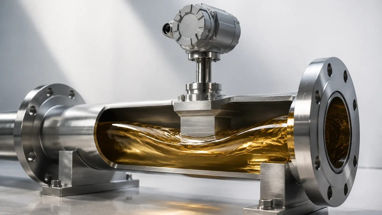
For liquid HTF applications, the meter should ideally be installed in a vertical pipe with the flow moving upward. This ensures the pipe is always full and prevents entrained air from collecting at the sensor. If horizontal installation is necessary, the sensor should be oriented to avoid the top of the pipe (where air bubbles collect) and the bottom (where sediment may settle).
Operational Limitations and Troubleshooting
Even the best-engineered system can encounter issues. Common problems with HTF flow measurement include:
* Cavitation: If the pressure at the flow meter drops below the vapor pressure of the fluid, vapor bubbles will form and collapse. This causes erratic readings and can physically erode the meter's internals. Always ensure sufficient back-pressure at the meter location.
* Fluid Degradation (Coking): Over time, HTFs can break down if overheated, forming carbon deposits known as "coke." These deposits can coat the sensors of ultrasonic meters or clog the impulse lines of DP meters. Regular fluid analysis is necessary to monitor the health of the HTF.
* Signal Drift: In high-temperature environments, thermal cycling can cause electronic components to drift. Periodic zero-point verification is recommended.
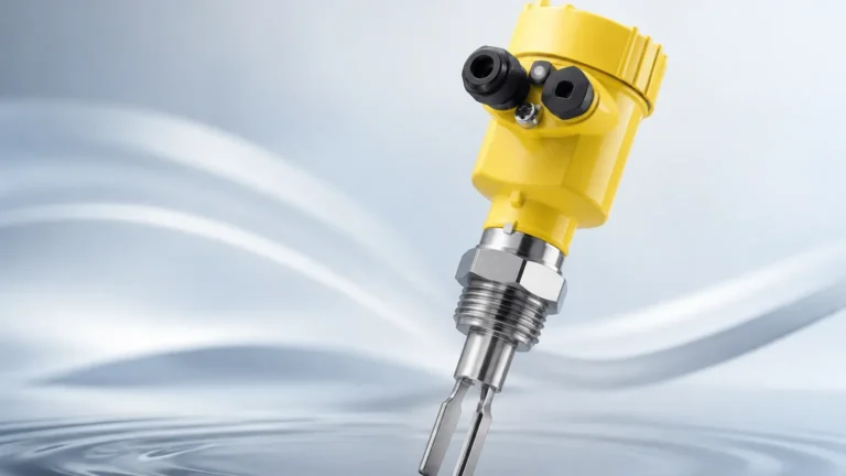
While flow measurement is vital for process control, it is only one part of a comprehensive instrumentation strategy. For a complete overview of measurement solutions for industrial tanks and thermal fluid systems, including level switches and transmitters for expansion tanks, visit the Main Page.
Maintenance and Calibration
Maintenance requirements for a heat transfer fluids flow meter vary by technology. Vortex and Ultrasonic meters are largely maintenance-free due to the lack of moving parts. However, DP meters require regular inspection of the orifice plate for wear or rounding of the sharp edge, which will degrade accuracy.
Calibration should be performed using a fluid that mimics the operating Reynolds number of the application. Since it is difficult to calibrate with hot oil in a lab setting, many manufacturers provide "dry calibration" methods or use water-based calibration with mathematical offsets for temperature and viscosity.
Frequently Asked Questions (FAQs)
Q: Can I use a standard water flow meter for thermal oil?
A: Generally, no. Standard meters often use seals (like EPDM) that will dissolve in thermal oil, and their electronics are rarely rated for the high ambient heat radiated by HTF piping.
Q: Why is my vortex meter reading zero when the pump is running?
A: This is common during cold starts. If the oil is too thick (high viscosity), it may not shed vortices properly, or the flow rate may be below the meter's minimum cutoff. Once the oil heats up and thins, the meter should begin functioning.
Q: How do I measure the energy (BTU/kW) being transferred?
A: You need three measurements: mass flow rate, the temperature of the fluid entering the process (supply), and the temperature of the fluid leaving the process (return). Many modern flow computers can take these inputs and calculate real-time energy transfer based on the specific heat capacity of your HTF.
Q: Is a clamp-on ultrasonic meter accurate enough for HTF?
A: Clamp-on meters are excellent for check-metering and balancing. However, for critical custody transfer or precise boiler control, an in-line meter (Vortex or Coriolis) is usually preferred due to the potential for signal attenuation at high temperatures with clamp-on transducers.
Conclusion
Selecting a heat transfer fluids flow meter requires a balance between accuracy requirements, budget, and the physical realities of high-temperature operation. For most industrial thermal oil loops, Vortex meters offer the best balance of durability and cost. For applications requiring extreme precision or energy balancing, Coriolis mass flow meters are the gold standard. Regardless of the technology chosen, paying close attention to Reynolds numbers, viscosity changes, and mechanical installation will ensure a reliable measurement system that contributes to the safety and efficiency of the industrial process.