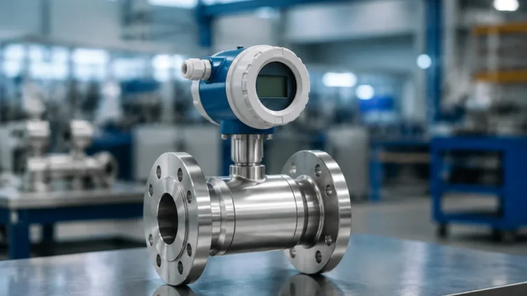
Vega Vibrating Level Switch
Vega Vibrating Level Switch
In the landscape of industrial automation, point level detection serves as a critical safety and process control mechanism. Among the various technologies available, the vibrating level switch—often referred to as a tuning fork sensor—is recognized for its reliability and versatility. This article examines the engineering principles, application criteria, and installation requirements of the Vega vibrating level switch and similar high-performance industrial level instruments.
Point level switches are designed to detect the presence or absence of a medium at a specific height within a vessel or pipe. Unlike continuous level measurement, which provides a constant tracking of the level, a vibrating level switch acts as a limit signal, triggering alarms for overfill protection or dry-run prevention for pumps. For engineers seeking a broader range of industrial solutions, visiting the Main Page provides a comprehensive overview of available technologies including radar and ultrasonic sensors.
Measurement Principle: The Physics of Vibration
The fundamental operation of a vibrating level switch relies on the change in resonant frequency when a vibrating element is immersed in a medium. The sensor consists of two main components: a mechanical vibrating fork and an internal drive assembly.
Piezoelectric Excitation
Inside the sensor housing, a piezoelectric crystal is energized by an electronic circuit. This crystal converts electrical energy into mechanical movement, causing the tuning fork to vibrate at its natural resonant frequency in the air. For liquid applications, this frequency is typically around 1,200 Hz, while for solid applications (vibrating rods or forks), the frequency may differ based on the design.
Frequency Shift Detection
When the medium (liquid or solid) comes into contact with the vibrating fork, the physical mass of the medium dampens the vibration, causing a significant shift in the resonant frequency.
1. In Air: The fork vibrates freely at its calibrated frequency.
2. In Medium: The density of the liquid or solid increases the effective mass of the vibrating system, lowering the frequency.
3. Signal Processing: The integrated electronics monitor this frequency continuously. Once the frequency drops below a predefined threshold, the electronics trigger a switching output (such as a relay, transistor, or NAMUR signal).
Because this principle relies on mechanical vibration rather than electrical properties like conductivity or dielectric constants, the vega vibrating level switch is largely unaffected by the chemical or physical properties of the medium, provided the density is within the sensor's operating range.
Key Evaluation Criteria for Selection
Selecting the correct vibrating level switch requires a detailed understanding of the process environment. While these sensors are robust, specific configurations are necessary for different industrial demands.
1. Media Type: Liquids vs. Solids
Vibrating switches are categorized by the type of media they are intended to detect.
* Liquid Switches: Usually feature a compact tuning fork design. They are optimized for low-viscosity fluids and can handle turbulence or bubbles.
* Solid Switches: Often utilize a single-rod or a larger, more robust fork design to prevent material buildup between the tines. These are used for powders, grains, and granules.
2. Density and Viscosity
The minimum density of the medium is a critical specification. Standard switches can typically detect liquids with a density as low as 0.7 g/cm³ (700 kg/m³), though specialized versions exist for lighter hydrocarbons down to 0.5 g/cm³. Viscosity is also a factor; while vibrating forks can handle viscosities up to 10,000 mPa·s, extremely thick media may cause "bridging" between the fork tines, leading to false positives.
3. Process Temperature and Pressure
Standard industrial models usually operate between -50°C and +150°C. For extreme applications, such as steam boilers or cryogenic storage, high-temperature extensions with cooling fins are required to protect the electronics. Pressure ratings typically range from vacuum up to 64 bar (6.4 MPa), depending on the flange or thread type.
4. Material Compatibility
The wetted parts must be resistant to the process medium. 316L stainless steel is the standard, but for corrosive chemical environments, coatings like PFA or exotic metals like Hastelloy C22 are used.
Practical Selection Table
| Feature | Liquid Application (e.g., VEGASWING) | Solid Application (e.g., VEGAVIB / WAVE) |
| :— | :— | :— |
| Primary Goal | Overfill/Dry-run protection | High/Low level bulk detection |
| Density Limit | > 0.5 g/cm³ to 0.7 g/cm³ | > 0.008 g/cm³ (for light powders) |
| Max Viscosity | 10,000 mPa·s | N/A (Flowability is key) |
| Build-up Resistance | High (vibration sheds light coating) | Moderate (requires single rod for sticky solids) |
| Typical Mounting | G1, G3/4, or Flange | G1½, Flange, or NPT |
Installation Considerations and Best Practices
Correct installation ensures the longevity of the sensor and the accuracy of the signal. Engineers should follow these guidelines during the design and commissioning phases.
Orientation and Positioning
* Side Mounting: When installed horizontally, the tines of the fork should be oriented vertically (standing on edge). This prevents the medium from resting on the flat surface of the tines, which could lead to false switching or material buildup.
* Top Mounting: For high-level alarms, the sensor is mounted vertically from the top. The length of the extension tube determines the switching point.
* Flow Direction: In piping applications, the fork should be aligned so that the tines are parallel to the flow direction to minimize resistance and prevent mechanical stress.
Avoiding False Triggers
The sensor should not be placed directly in the path of a filling stream. The mechanical force of the falling material can cause premature wear or false signals. If the sensor must be near an inlet, a protective baffle or shield should be installed above the fork.
Electrical Wiring
Most vibrating level switches offer universal power supply options (20…253 V AC/DC). It is vital to ensure that the cable gland is tightened correctly and the cable loops downward before entering the housing (a "drip loop") to prevent moisture from entering the electronics compartment via capillary action.

Limitations and When to Choose Alternatives
While the vega vibrating level switch is a "workhorse" of the industry, it is not a universal solution for every scenario.
* Heavy Build-up: In applications with extremely sticky media that can bridge the gap between the fork tines (e.g., thick syrups or wet clay), the sensor may fail to return to its natural frequency even when the vessel is empty. In these cases, a single-rod vibrating sensor or a capacitive level switch may be more appropriate.
* Large Granules: In silos containing very large rocks or heavy ores, the mechanical impact of the material can damage the tuning fork. Heavy-duty radar or ultrasonic sensors are often preferred for these non-contact applications.
* Aerated Liquids: If a liquid is highly aerated or contains a high volume of gas bubbles, the effective density may drop below the sensor's detection threshold, leading to a failure to switch.
Frequently Asked Questions (FAQ)
Q: Does the vibrating level switch require calibration?
A: Generally, no. Most units are factory-calibrated to detect standard liquid or solid densities. Some models feature a small DIP switch to adjust sensitivity for very low-density media, but field calibration against the medium is rarely necessary.
Q: Can these sensors be used in hazardous areas?
A: Yes, vibrating level switches are frequently available with ATEX, IECEx, and FM certifications for use in explosive atmospheres (Ex d, Ex ia, etc.).
Q: How do I test the function of the switch without filling the tank?
A: Many modern switches include a test button or a magnetic test point on the housing. Touching this point simulates a dampened state, allowing the operator to verify that the downstream alarms and relays are functioning correctly.
Q: What is the typical lifespan of a vibrating level switch?
A: Because there are no rotating parts or seals subject to friction, these sensors can last for over 10 years in non-corrosive environments. The primary failure points are electronic surges or extreme mechanical impact.
Conclusion
The vega vibrating level switch represents a mature, reliable technology for point level detection across the water treatment, chemical, and food industries. By understanding the mechanical resonance principle and selecting materials and mounting positions carefully, engineers can implement a maintenance-free solution for critical process safeguards. For more information on integrating these sensors into a broader automation strategy or to explore alternative measurement technologies, please refer to the Main Page for technical support and product specifications.