How to Calibrate Pressure Transducer
How to Calibrate Pressure Transducer
In industrial process control, the accuracy of pressure and level measurements is paramount for safety, efficiency, and quality assurance. Pressure transducers serve as the eyes of a control system, converting physical force into an electrical signal. However, environmental factors, mechanical wear, and electronic drift can cause these instruments to deviate from their factory settings over time. Understanding how to calibrate pressure transducer units is a critical skill for maintenance engineers and technicians working with Welk industrial instrumentation. This guide provides a comprehensive technical overview of the principles, equipment, and procedures required to maintain measurement integrity.
The Fundamental Principles of Pressure Transducers
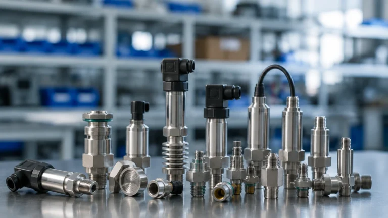
Before diving into the calibration process, it is essential to understand the underlying technology. Most modern industrial pressure transducers, such as those used in hydrostatic level measurement, rely on one of two primary sensing principles: piezoresistive or capacitive sensing.
Piezoresistive Sensing
In a piezoresistive transducer, a diaphragm is equipped with strain gauges. When pressure is applied, the diaphragm deforms, changing the electrical resistance of the gauges. This change is proportional to the applied pressure. These sensors are highly sensitive and widely used in water treatment and chemical processing due to their robust nature.
Capacitive Sensing
Capacitive transducers measure the change in electrical capacitance between a sensing diaphragm and a fixed reference plate. As pressure moves the diaphragm, the distance between the plates changes, altering the capacitance. These are often preferred for high-accuracy applications and low-pressure ranges.
The Relationship Between Pressure and Level
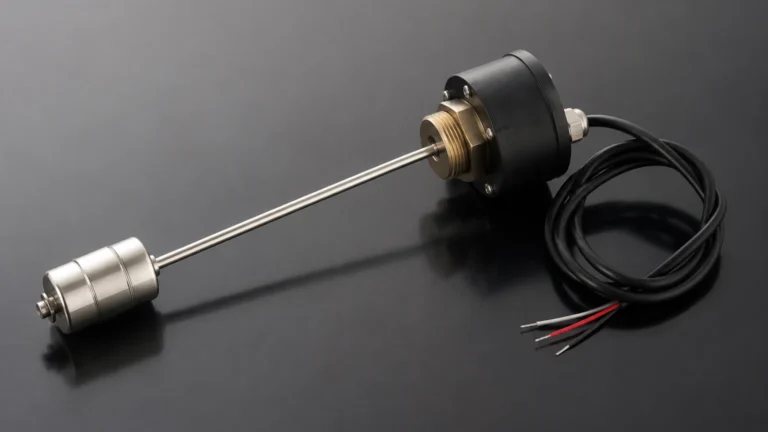
In many applications, pressure transducers are used to measure liquid level. This is based on the hydrostatic principle: $P = \rho \times g \times h$, where $P$ is pressure, $\rho$ is the density of the liquid, $g$ is gravity, and $h$ is the height of the liquid column. For example, a water column of 10 meters (32.8 feet) exerts approximately 0.98 bar (14.2 psi) of pressure at the base. Calibrating the transducer ensures that the electrical output (typically 4-20mA) correctly maps to both the pressure and the corresponding level.
Preparation and Required Calibration Equipment
To perform a professional calibration, you must use reference standards that are significantly more accurate than the device under test (DUT). Typically, the reference should be at least four times more accurate than the transducer.
Essential Tools
1. Regulated Pressure Source: A hand pump, nitrogen cylinder with a regulator, or a deadweight tester capable of reaching the maximum range of the transducer.
2. Reference Pressure Gauge: A high-precision digital manometer or master gauge with a current calibration certificate.
3. Power Supply: Most industrial transducers require a stable DC power source, typically 24V DC.
4. Multimeter or Process Calibrator: To measure the output signal (e.g., 4-20mA or 0-10V).
5. HART Communicator (Optional): Required for "Smart" transmitters to adjust digital parameters and perform sensor trims.
6. Fittings and Tubing: High-pressure rated hoses and leak-proof connectors (NPT or BSP threads).
A Detailed Procedure for Calibrating Pressure Transducers
The goal of calibration is to verify and adjust the "Zero" and "Span" of the instrument. The following steps outline a standard 5-point calibration check, which evaluates the linearity and hysteresis of the device.
Step 1: Safety and Isolation
Before removing a transducer from a process line, ensure the system is depressurized and isolated. If the medium is hazardous (chemical or oil and gas), follow all site-specific decontamination protocols.
Step 2: Setup and Warm-up
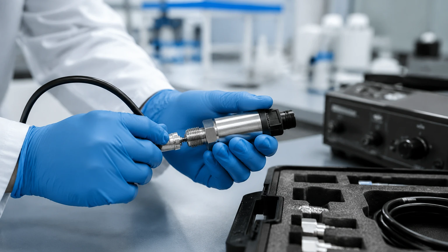
Connect the transducer to the pressure source and the reference gauge. Connect the electrical output to the multimeter or process calibrator. Power the unit and allow it to warm up for at least 15 minutes to stabilize the internal electronics.
Step 3: The Zero Adjustment
With the transducer vented to the atmosphere (0 bar / 0 psi), check the output signal. For a 4-20mA transmitter, the reading should be exactly 4.000mA. If it deviates, use the zero adjustment screw or the digital interface to bring it back to the target value.
Step 4: The 5-Point Calibration Check
Apply pressure in increments to verify the linearity of the transducer. Record the output at the following points:
* 0% (Lower Range Value): 4.00mA
* 25%: 8.00mA
* 50%: 12.00mA
* 75%: 16.00mA
* 100% (Upper Range Value): 20.00mA
After reaching 100%, repeat the measurements in descending order (75%, 50%, 25%, 0%) to check for hysteresis—the difference in output for the same pressure depending on the direction of change.
Step 5: Span Adjustment
If the reading at 100% pressure is incorrect (e.g., 19.8mA instead of 20.0mA), adjust the "Span" or "Gain" setting. Note that adjusting the span can sometimes affect the zero point, so it is often necessary to iterate between zero and span adjustments until both are accurate.
Bench Calibration vs. Field Calibration Methods
Deciding where to perform the calibration depends on the accuracy requirements and the operational environment.
| Feature | Bench Calibration | Field (In-Situ) Calibration |
| :— | :— | :— |
| Environment | Controlled (Constant temp/humidity) | Process conditions (Variable) |
| Accuracy | Highest; ideal for master gauges | Practical; accounts for installation effects |
| Equipment | Heavy/fixed (Deadweight testers) | Portable (Hand pumps/calibrators) |
| Downtime | Requires instrument removal | Performed on-site, often faster |
| Best For | Annual certification, high-precision tasks | Routine maintenance, verification |
For critical industrial automation applications, Welk recommends a bench calibration for initial commissioning, followed by regular field verifications to ensure process stability. For more detailed technical specifications on our range of instruments, you can visit our Main Page.
Installation Considerations for Long-Term Accuracy
Even a perfectly calibrated transducer will provide inaccurate data if installed incorrectly. When mounting pressure transducers for level or process measurement, consider the following:
1. Mounting Position: The orientation of the diaphragm can affect the zero point due to the weight of the internal fill fluid. Always calibrate the unit in the same orientation it will be installed.
2. Impulse Piping: Keep impulse lines as short as possible to minimize lag. For liquid service, slope the lines downward toward the transducer to prevent air bubbles from being trapped.
3. Temperature Effects: Extreme heat or cold can cause thermal expansion in the sensor. Use siphons or cooling spacers if the process temperature exceeds the rated limit (typically 80°C / 176°F for standard models).
4. Atmospheric Venting: Gauge pressure transducers require a vent to the atmosphere (usually through the cable or a breather plug). Ensure this vent is not blocked by debris or moisture, as this will cause significant drift.
Troubleshooting Common Calibration Issues
If you encounter difficulties during the process of how to calibrate pressure transducer units, check for these common industrial issues:
* Non-Linearity: If the 0% and 100% points are correct but the mid-points (50%) are off, the sensor diaphragm may be damaged or coated with process buildup. Cleaning the diaphragm with a soft cloth and compatible solvent may resolve this.
* Drift: If the zero point shifts frequently, it may be due to moisture ingress in the housing or extreme temperature fluctuations. Check the IP rating of the enclosure and ensure cable glands are tight.
* Hysteresis: Significant differences between upscale and downscale readings often indicate mechanical fatigue in the diaphragm or a leak in the calibration test setup.
* Unstable Output: Erratic mA readings are usually caused by electrical noise or a faulty power supply. Ensure the signal cable is shielded and grounded at one end only.
Selection Criteria for Pressure Transducers
Choosing the right instrument reduces the frequency of required calibrations. Use the table below to evaluate common industrial requirements.
| Application | Recommended Sensor Type | Key Advantage |
| :— | :— | :— |
| Water Treatment | Submersible Hydrostatic | Easy installation in open tanks |
| Chemical Processing | Flush Diaphragm | Prevents clogging from viscous fluids |
| Oil & Gas | Explosion-Proof Piezoresistive | High safety rating and durability |
| Food & Beverage | Sanitary (Tri-clamp) | Easy to clean (CIP/SIP compatible) |
| High-Pressure Steam | Differential Pressure with Siphon | Protects sensor from high temperatures |
Frequently Asked Questions (FAQ)
Q: How often should I calibrate my pressure transducer?
A: Most industrial standards suggest an annual calibration. However, for critical safety systems or harsh environments with high vibration and temperature cycling, semi-annual or quarterly checks may be necessary.
Q: Can I calibrate a transducer using only a multimeter?
A: A multimeter can only measure the output. You still need a traceable pressure source and a reference gauge to perform a true calibration. Without a known pressure input, you are only performing a loop check, not a calibration.
Q: What is the difference between a "Zero Trim" and a "Calibration"?
A: A zero trim is a simple adjustment to correct for mounting position or atmospheric shifts at zero pressure. A full calibration involves testing multiple points across the entire range of the instrument to ensure linearity and span accuracy.
Q: Does the length of the cable affect calibration?
A: For 4-20mA current loops, cable length has minimal impact on accuracy over long distances (up to several hundred meters). For voltage output transducers (0-10V), cable resistance can cause significant voltage drops, making local calibration or 4-wire configurations essential.
By following these technical guidelines, operators can ensure that their Welk level measurement and pressure sensing equipment remains accurate throughout its operational life. Proper calibration not only extends the lifespan of the instrument but also safeguards the integrity of the entire industrial process.