Aquaculture Sensors
Aquaculture Sensors
In modern industrial aquaculture, precision is the foundation of sustainability and profitability. Whether managing Recirculating Aquaculture Systems (RAS), traditional pond farming, or offshore cages, the ability to monitor water levels, feed inventory, and chemical storage is critical. Aquaculture sensors designed for level measurement provide the continuous data stream necessary for automated control systems, ensuring that fish stocks remain in optimal environments while reducing manual labor and operational risks.
Effective level monitoring prevents catastrophic events such as tank overflows, pump dry-running, and oxygen depletion caused by unexpected volume changes. This guide explores the engineering principles, selection criteria, and installation strategies for level sensors within the aquaculture sector.
The Importance of Level Monitoring in Modern Aquaculture
Aquaculture environments are dynamic. In RAS facilities, water moves through various filtration and treatment stages where maintaining a precise head of water is essential for the gravity-fed portions of the system. In outdoor pond farming, monitoring water levels helps manage evaporation and prevents flooding during heavy rainfall.
Beyond water management, aquaculture sensors are vital for inventory control. Large-scale operations rely on bulk silos for fish feed; level sensors in these silos ensure that feed supplies are replenished before they run out, preventing growth delays. Furthermore, chemical tanks used for water treatment and disinfection require constant monitoring to ensure the safety and efficacy of the treatment process. For comprehensive equipment options and technical support in these areas, engineers often consult the Main Page of specialized manufacturers to match sensor specifications with site-specific needs.
Measurement Principles for Aquaculture Level Sensors
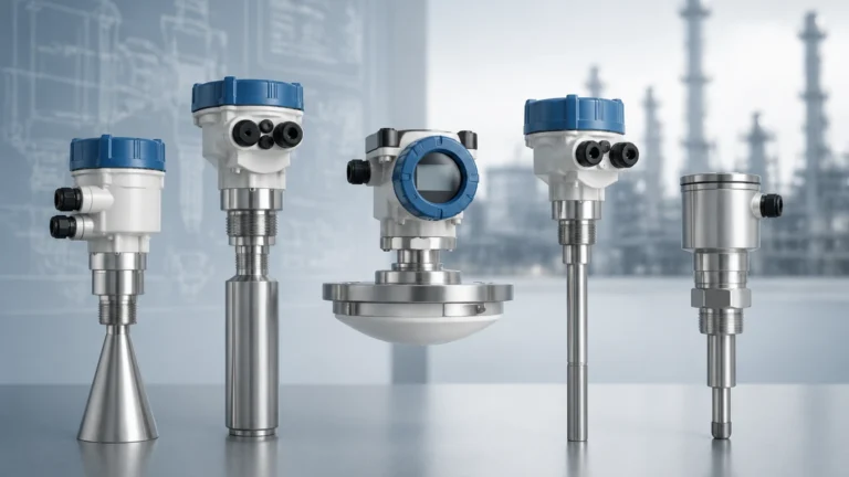
Choosing the right aquaculture sensor requires an understanding of the underlying physics used to detect the surface of a liquid or solid. The following technologies are the most prevalent in the industry:
1. Ultrasonic Level Sensors (Non-Contact)
Ultrasonic sensors emit high-frequency sound pulses that travel through the air, reflect off the water surface, and return to the transducer. The sensor calculates the distance based on the time-of-flight.
* Principle: $Distance = (Speed of Sound \times Time) / 2$.
* Suitability: Excellent for clean water tanks and sumps where the sensor can be mounted safely above the liquid.
2. Radar Level Sensors (Non-Contact)
Radar sensors, particularly those operating at 26GHz or 80GHz, use high-frequency electromagnetic waves. Unlike sound, these waves are unaffected by air temperature fluctuations, steam, or heavy dust.
* Principle: Frequency Modulated Continuous Wave (FMCW) or pulse technology measures the time it takes for the microwave signal to return.
* Suitability: Ideal for feed silos (where dust is prevalent) and outdoor ponds where wind and temperature changes might interfere with ultrasonic signals.
3. Hydrostatic Pressure Transmitters (Contact)
These sensors are submerged at the bottom of a tank or pond. They measure the pressure exerted by the liquid column above them.
* Principle: $P = \rho gh$ (Pressure = Density × Gravity × Height).
* Suitability: Best for deep reservoirs or tanks with surface foam that might confuse non-contact sensors. They provide a direct measurement of the water column height regardless of surface conditions.
4. Level Switches (Point Level)
While continuous sensors provide a range (e.g., 0–10 meters), level switches provide a binary signal (on/off). Magnetic float switches or tuning fork switches are commonly used for high-level alarms or pump protection.
Comparison of Level Measurement Technologies
Selecting a sensor involves balancing accuracy, maintenance requirements, and cost. The following table provides a comparison for common aquaculture applications.
| Technology | Typical Accuracy | Best Application | Key Advantage | Limitation |
| :— | :— | :— | :— | :— |
| Ultrasonic | ±0.25% of range | Clean water tanks | Cost-effective, non-contact | Affected by foam and vapor |
| Radar (80GHz) | ±2 mm (0.08 in) | Feed silos, chemical tanks | High precision, ignores dust | Higher initial investment |
| Hydrostatic | ±0.1% to 0.5% | Deep ponds, RAS sumps | Simple installation, ignores foam | Requires submersion; cleaning needed |
| Level Switch | N/A | Overflow/Dry-run alarm | High reliability, low cost | Point level only; no trend data |
Selection Criteria: Material Compatibility and Environmental Factors
Aquaculture environments are notoriously harsh on electronic components. When specifying aquaculture sensors, engineers must consider the following factors:
Salinity and Corrosion
In marine aquaculture, sensors are exposed to saltwater and salt spray. Standard stainless steel (304) will corrode quickly. It is essential to use high-grade materials such as 316L stainless steel, Titanium, or plastic housings (PP/PTFE) for non-contact sensor faces. For hydrostatic sensors, the cable jacket must be made of chemically resistant materials like PUR (Polyurethane) or FEP to prevent degradation.
Biofouling
Submerged sensors, such as hydrostatic transmitters, are prone to biofouling. Algae, barnacles, and biofilm can grow on the sensor diaphragm, leading to measurement drift or total failure. In these cases, sensors with flush diaphragms or specialized coatings are preferred to make cleaning easier and reduce the frequency of maintenance.
Power and Signal Integration
Most industrial aquaculture sensors output a standard 4-20mA signal or use digital protocols like RS485 (Modbus). In remote pond locations, low-power sensors that can operate on 12V DC solar systems are critical. Integration into a centralized PLC (Programmable Logic Controller) or SCADA system allows for real-time monitoring and automated alerts.

Installation Best Practices for Tank and Pond Monitoring
Proper installation is as important as the sensor technology itself. Poor placement can lead to false readings and premature hardware failure.
1. Avoid Obstructions: For radar and ultrasonic sensors, ensure the signal beam is clear of ladders, pipes, or aerators. A 26GHz radar typically has a wider beam angle than an 80GHz radar; the latter is better for narrow tanks.
2. Stilling Wells: In tanks with high turbulence or surface agitation from aerators, installing the sensor inside a stilling well (a vertical pipe) can stabilize the liquid surface and provide a much cleaner signal for hydrostatic and ultrasonic sensors.
3. Venting for Hydrostatic Sensors: Hydrostatic sensors use a vent tube in the cable to compensate for changes in atmospheric pressure. This vent must be protected by a moisture filter or terminated in a dry junction box to prevent condensation from entering the sensor internals.
4. Mounting Height: Non-contact sensors should be mounted at a height that accounts for the "dead zone" (the area immediately below the sensor where it cannot measure). For a typical ultrasonic sensor, this might be 0.25m to 0.5m (10 to 20 inches).
Addressing Technical Challenges: Biofouling and Signal Interference
Managing Surface Agitation
Aeration is vital for fish health but creates surface bubbles and waves that can scatter ultrasonic signals. If a stilling well cannot be used, radar sensors are generally more robust in these conditions because microwaves penetrate foam more effectively than sound waves.
Lightning and Surge Protection
Outdoor ponds are often located in open areas prone to lightning strikes. Sensors should be equipped with internal surge protection, and signal lines should be shielded and properly grounded to prevent induced voltages from destroying the sensitive electronics during a storm.
Temperature Compensation
The speed of sound changes with air temperature. If using ultrasonic sensors outdoors, ensure the sensor has a built-in temperature probe to automatically compensate for these changes, otherwise, the level reading may drift by several centimeters between day and night.
Frequently Asked Questions (FAQ)
Q: Can I use a standard level sensor in a saltwater tank?
A: Only if the wetted parts are compatible. For saltwater, 316L stainless steel is the minimum requirement, but PTFE or Titanium is recommended for long-term submersion to prevent pitting corrosion.
Q: How often do aquaculture sensors need calibration?
A: This depends on the technology. Hydrostatic sensors should be checked every 6–12 months for drift caused by biofouling. Radar and ultrasonic sensors are generally more stable but should be verified annually against a manual measurement.
Q: What is the best sensor for measuring fish feed in a silo?
A: High-frequency (80GHz) radar is the industry standard for solids. It can penetrate the dust generated during silo filling and accurately measure the steep angles (angle of repose) of the feed pellets.
Q: How do I protect submerged sensors from fish or aquatic life?
A: In cages or ponds, hydrostatic sensors should be placed inside a perforated PVC pipe. This protects the sensor from physical impact while allowing water to pass through freely for accurate pressure measurement.
Conclusion
Implementing the right aquaculture sensors is a strategic investment that enhances the reliability of fish farming operations. By understanding the specific needs of the environment—from the corrosive nature of seawater to the physical challenges of feed dust—operators can select level measurement solutions that provide long-term accuracy. For those seeking to optimize their systems with professional-grade instrumentation, reviewing detailed technical specifications on the Main Page is a recommended next step to ensure the chosen hardware meets the rigorous demands of industrial aquaculture.