Hydraulic Oil Level Switch
Hydraulic Oil Level Switch
Hydraulic systems are the backbone of modern industrial machinery, providing the force necessary for everything from plastic injection molding to heavy construction equipment. At the heart of these systems is hydraulic fluid, which must be maintained at specific levels to ensure operational efficiency and component longevity. A hydraulic oil level switch serves as a critical diagnostic and safety component, designed to monitor the fluid level within a reservoir and trigger an alert or system shutdown if the oil falls below a safe threshold or exceeds a maximum limit.
In industrial automation and fluid power applications, the failure to detect a low-oil condition can lead to pump cavitation, overheating, and catastrophic mechanical failure. Conversely, overfill detection prevents environmental contamination and safety hazards caused by spills. This guide provides a technical overview of the measurement principles, selection criteria, and installation best practices for hydraulic oil level switches used in professional engineering environments.
Core Measurement Principles for Hydraulic Oil
Before selecting a specific device, it is essential to understand the physics behind the sensing technologies. Hydraulic oil presents unique challenges, including varying viscosity, potential for aeration (foaming), and high operating temperatures. The following technologies are the most prevalent in industrial applications.
1. Magnetic Float Principle
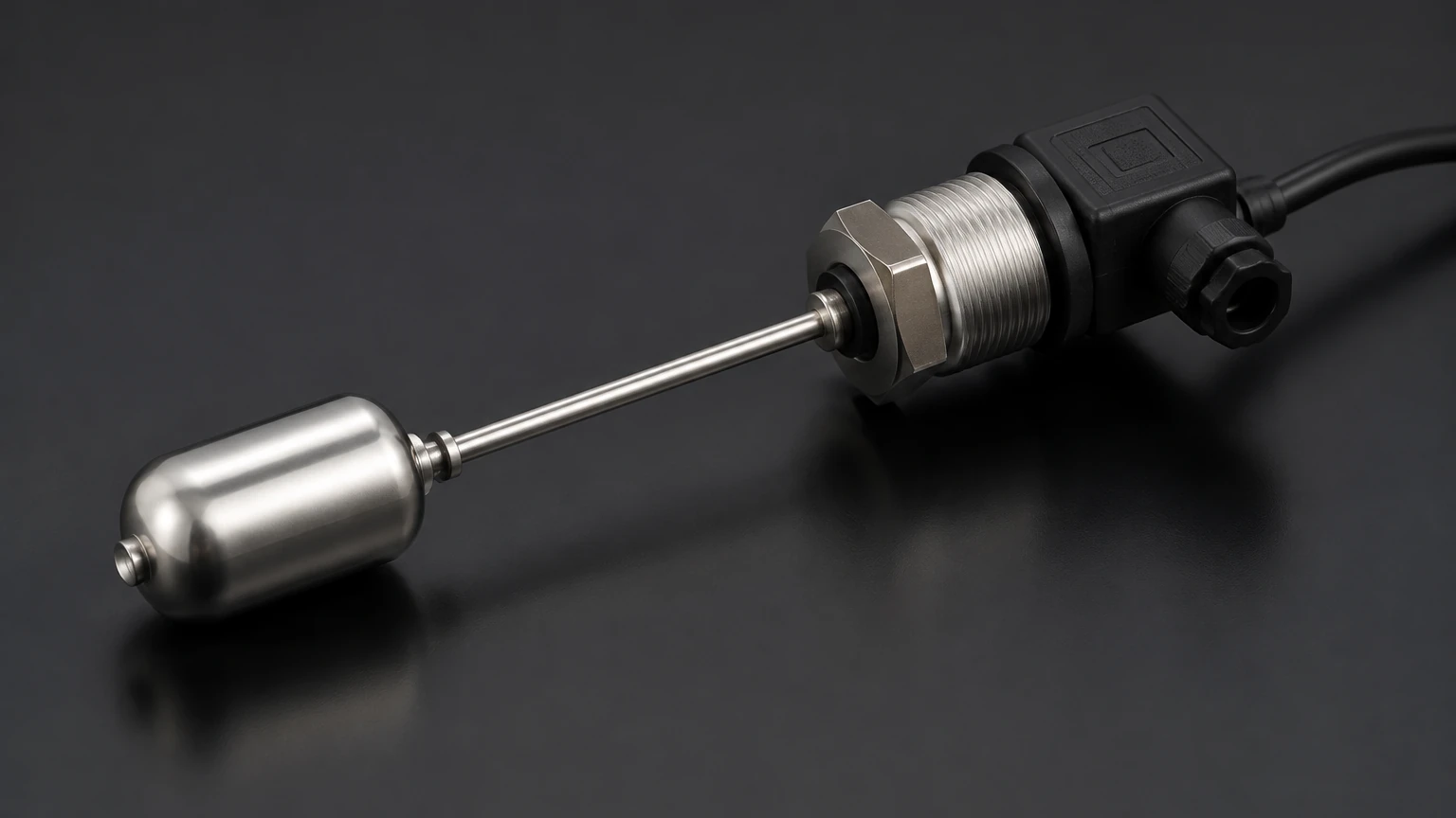
This is the most common technology for hydraulic reservoirs due to its simplicity and reliability. A magnetic float switch consists of a hollow float containing a permanent magnet and a stationary stem containing one or more reed switches. As the oil level rises or falls, the float travels along the stem. When the magnet inside the float reaches the position of the reed switch, the magnetic field causes the switch contacts to open or close.
* Advantages: Low cost, requires no external power for the switch itself (passive), and is highly compatible with most mineral-based oils.
* Considerations: Moving parts can be affected by heavy sludge or metallic particles (swarf) in the oil.
2. Optical Sensing Principle
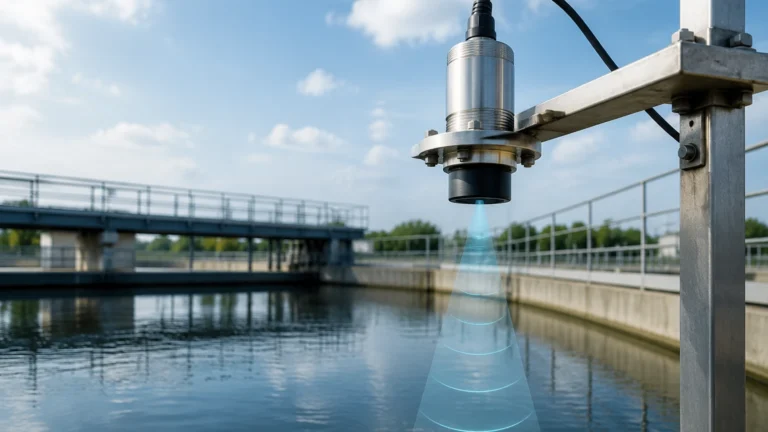
Optical level switches utilize an infrared LED and a phototransistor. These components are housed within a plastic or glass prism at the tip of the sensor. When the sensor tip is in the air (low oil level), the infrared light from the LED is reflected back within the prism to the receiver. When the tip is submerged in oil, the light is refracted into the liquid, causing the receiver to detect a change in light intensity.
* Advantages: No moving parts, very compact footprint, and extremely fast response times.
* Considerations: Can be affected by heavy foaming or thick coatings of aged oil on the prism.
3. Capacitive Sensing Principle
Capacitive switches measure the change in electrical capacitance between two electrodes (or one electrode and the tank wall) as the oil level changes. Because hydraulic oil has a different dielectric constant (typically 2.1 to 2.5) than air (1.0), the sensor can detect the presence of fluid with high precision.
* Advantages: No moving parts; can be designed to sense through non-metallic tank walls.
* Considerations: Requires calibration to the specific dielectric constant of the oil; sensitive to moisture contamination in the oil.
4. Vibrating Fork (Tuning Fork) Principle
The sensor element consists of a fork that is piezoelectrically vibrated at its resonant frequency. When the fork is immersed in hydraulic oil, the frequency of vibration changes. This change is detected by the electronics and converted into a switching signal.
* Advantages: Highly resistant to bubbles, turbulence, and changes in oil viscosity.
* Considerations: Generally more expensive than float or optical switches; requires a larger mounting footprint.
Key Evaluation Criteria for Selection
Choosing the correct hydraulic oil level switch requires a detailed assessment of the operating environment. Engineers should evaluate the following parameters before procurement:
Fluid Compatibility and Viscosity
Hydraulic fluids range from standard mineral oils to fire-resistant synthetic esters and water-glycol mixtures. Ensure the wetted materials of the switch (e.g., Stainless Steel 304/316, NBR, or Polypropylene) are chemically compatible with the specific fluid. High-viscosity oils in cold-start conditions may impede the movement of mechanical floats, making non-contact or solid-state sensors more appropriate.
Temperature and Pressure Ratings
Hydraulic reservoirs typically operate at atmospheric pressure, but the oil temperature can reach 80°C (176°F) or higher in heavy-duty cycles. The switch must be rated for the maximum possible system temperature to prevent seal failure or electronic drift. In pressurized reservoirs, the switch must also meet the specific Bar (or PSI) requirements of the tank.
Electrical Output and Integration
Decide whether the system requires a simple dry contact (SPST or SPDT) or a solid-state output (PNP/NPN). For safety-critical applications, "normally closed" (NC) logic is often preferred so that a broken wire or power failure triggers a system alarm (fail-safe).
Technical Selection Table
The following table compares the most common technologies for hydraulic oil level monitoring to assist in the initial engineering phase.
| Feature | Magnetic Float | Optical Switch | Capacitive Switch | Vibrating Fork |
| :— | :— | :— | :— | :— |
| Moving Parts | Yes | No | No | No (Micro-vibration) |
| Max Temp (Typical) | 120°C | 100°C | 125°C | 150°C |
| Max Pressure | 10 – 40 Bar | 50 Bar | 20 Bar | 64 Bar |
| Viscosity Limit | Low to Medium | Low to High | Medium | Very High |
| Foam Resistance | Good | Fair | Poor | Excellent |
| Relative Cost | Low | Medium | Medium | High |
For comprehensive system design, engineers often consult the Main Page of specialized instrument manufacturers to review specific model certifications and technical drawings.
Installation Guidelines and Best Practices
Proper installation is as important as sensor selection. Incorrect placement can lead to false alarms or delayed response during critical level drops.
1. Avoid the Splash Zone: Do not install the level switch directly under a return line or near the oil fill port. Turbulence and splashing can cause the switch to "chatter" or provide inconsistent readings.
2. Stilling Wells: If the reservoir experiences significant agitation, install the float switch inside a stilling well (a vertical pipe with small vent holes) to dampen the fluid movement and protect the sensor.
3. Orientation:
* Top-down mounting: Ideal for multi-point float switches that monitor high, low, and critical-low levels.
* Side mounting: Useful for single-point alarms in compact power units where vertical space is limited.
4. Magnetic Interference: Since many hydraulic switches use magnets, ensure they are mounted at least 50mm away from strong electromagnetic sources like large motors or solenoids to prevent interference with the reed switch.
5. Sealing: Use appropriate thread sealants (such as PTFE tape or bonded seals) compatible with hydraulic oil. For G-threaded (parallel) ports, ensure the O-ring or gasket is seated correctly to prevent leaks under the weight of the fluid column.
Operational Limitations and Risk Mitigation
While highly reliable, hydraulic oil level switches are subject to specific industrial risks:
* Aeration and Foaming: In high-cycle systems, oil can become aerated. Optical and ultrasonic sensors may struggle to distinguish between foam and liquid. If foaming is a known issue, a vibrating fork or a float switch with a weighted float is recommended.
* Varnish and Sludge: Over time, hydraulic oil can degrade, forming a sticky varnish. This can cause mechanical floats to stick in the "OK" position even when the level is low. Regular oil analysis and switch inspection are necessary.
* Metallic Contamination: In systems with significant wear, fine metallic particles can accumulate on magnetic float stems. Using a magnetic drain plug in the reservoir can help mitigate this risk, but non-magnetic sensing (like optical) is a safer alternative in high-wear environments.
Frequently Asked Questions (FAQs)
Q: Can a hydraulic oil level switch also measure temperature?
A: Yes, many modern industrial switches are "combi-sensors" that include a PT100 or PT1000 temperature probe within the same housing. This allows for simultaneous monitoring of oil level and thermal health through a single tank port.
Q: What is the difference between N/O and N/C in the context of oil levels?
A: "Normally Open" (N/O) means the circuit is open when the oil is at the "normal" level. "Normally Closed" (N/C) means the circuit is closed during normal operation. For low-level alarms, N/C is typically used as a fail-safe; if a wire is cut, the circuit opens, and the controller assumes a low-level fault has occurred.
Q: How often should these switches be tested?
A: In most industrial environments, a functional test should be performed every 6 to 12 months. This involves manually moving the float (if accessible) or partially draining the reservoir to ensure the control system receives the correct signal.
Q: Are these switches suitable for high-pressure hydraulic lines?
A: No. Level switches are designed for use in the reservoir (tank), which is typically at low or atmospheric pressure. For monitoring pressure in the actual lines, a pressure switch or transmitter is required.
Conclusion
The selection of a hydraulic oil level switch is a fundamental step in protecting expensive hydraulic infrastructure. By understanding the measurement principles—ranging from robust magnetic floats to sophisticated vibrating forks—engineers can match the sensor technology to the specific challenges of their application. Factors such as oil viscosity, temperature, and the presence of foam must dictate the final choice. For those seeking detailed specifications or customized solutions for industrial automation, visiting the Main Page provides access to a wider range of level measurement instruments and technical support to ensure system reliability and safety.