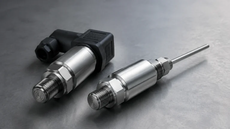
I O Link Sensors
I O Link Sensors
In the landscape of modern industrial automation, the transition from simple analog signaling to intelligent digital communication has become a cornerstone of Industry 4.0. Among the technologies driving this shift, IO-Link (standardized under IEC 61131-9) stands out as a robust, point-to-point communication protocol for sensors and actuators. For process industries requiring precise level measurement, i o link sensors represent a significant evolution, offering bi-directional data exchange that extends far beyond a traditional 4-20 mA or 0-10 V signal.
Welk, as a professional manufacturer of level measurement instruments, integrates IO-Link technology across its product range—including radar, ultrasonic, and hydrostatic transmitters—to provide operators with deeper insights into their processes. This guide explores the principles, selection criteria, and practical implementation of IO-Link enabled level sensors in industrial environments.
The Principle of IO-Link in Level Measurement
To understand the value of an IO-Link sensor, one must first distinguish between the physical measurement principle and the communication protocol. The physical principle (e.g., radar, ultrasonic, or pressure) determines how the level is detected, while IO-Link determines how that information is transmitted to the control system.
How IO-Link Works
IO-Link is not a fieldbus; it is a point-to-point communication link between a master device and a field device. An IO-Link system typically consists of an IO-Link master, which acts as a gateway to the higher-level PLC (Programmable Logic Controller) or fieldbus network (such as PROFINET or EtherNet/IP), and the individual sensors connected via standard unshielded 3-wire cables.
In a standard level sensor setup, the device transmits three types of data:
1. Process Data: The actual level measurement (e.g., 5.42 meters) and often a secondary value like temperature.
2. Service Data: Information about the sensor itself, such as manufacturer ID, serial number, and parameter settings.
3. Event Data: Error messages or maintenance warnings, such as "Low Signal Strength" or "Device Overheating."
Integration with Level Technologies
* Radar Level Meters: These sensors use Time of Flight (ToF) microwave pulses. When equipped with IO-Link, the sensor can transmit the distance to the media, the amplitude of the return echo (signal quality), and internal diagnostics to the PLC simultaneously.
* Ultrasonic Sensors: These use sound waves to measure distance. IO-Link allows for real-time adjustment of gain and filtering parameters to compensate for foam or turbulence without needing to access the sensor physically.
* Hydrostatic Transmitters: These measure the pressure exerted by a liquid column. IO-Link enables the transmission of both the pressure value and the media temperature, which is often required for density compensation.
Key Benefits of I O Link Sensors
Adopting i o link sensors provides several technical and economic advantages for B2B operations, particularly in water treatment, chemical processing, and industrial automation.
1. Enhanced Data Integrity
Unlike analog signals, which are susceptible to Electromagnetic Interference (EMI) and require shielded cables, IO-Link transmits data digitally. This eliminates the need for A/D conversion at the sensor and D/A conversion at the PLC, ensuring that the value measured by the sensor is exactly what the controller receives. This is critical for high-precision applications in the chemical and oil and gas sectors.
2. Remote Parameterization and Configuration
One of the most practical features of IO-Link is the ability to configure sensors from the control room. If a process change requires a different measurement range or a change in the switching point of a level switch, the parameters can be pushed from the PLC to the sensor. This reduces the need for technicians to climb tanks or enter hazardous areas for manual adjustments.
3. Automatic Device Replacement
When an IO-Link sensor is replaced, the IO-Link master can automatically recognize the new device and upload the configuration of the previous sensor to it. This "plug-and-play" capability significantly reduces downtime during maintenance cycles.
4. Advanced Diagnostics and Predictive Maintenance
IO-Link sensors provide continuous health monitoring. For example, a Welk radar level meter can report a decrease in signal strength caused by heavy buildup on the antenna. This allows maintenance teams to clean the sensor before it fails, moving from reactive to predictive maintenance strategies.
Selection Criteria for IO-Link Level Sensors
Choosing the right sensor requires balancing the process requirements with the capabilities of the IO-Link interface. Engineers should consult the Main Page of the manufacturer’s technical catalog to verify specific model compatibility.
Technical Specification Table
| Feature | Radar (80GHz) | Ultrasonic | Hydrostatic | Magnetic Gauge |
| :— | :— | :— | :— | :— |
| Measurement Range | Up to 120m | 0.1m – 15m | 1m – 200m H2O | 0.3m – 6m |
| Accuracy | ±1 mm | ±0.2% of range | ±0.1% to ±0.5% | ±5 mm |
| IO-Link Data | Distance, Signal, Temp | Distance, Echo Quality | Pressure, Temp | Level Position |
| Media Suitability | Liquids, Solids, Corrosives | Water, Wastewater | Liquids in tanks | Clean Liquids |
| Process Temp. | -40°C to +200°C | -20°C to +70°C | -10°C to +80°C | -20°C to +350°C |
Application Considerations
* Media Properties: For non-conductive liquids or materials with low dielectric constants, high-frequency radar is preferred. If the application involves simple water storage, ultrasonic sensors offer a cost-effective IO-Link solution.
* Tank Geometry: In narrow tanks with internal obstructions (ladders, agitators), radar sensors with narrow beam angles are easier to configure via IO-Link's false-echo suppression features.
* Environmental Factors: If the sensor will be exposed to high pressure or extreme temperatures, hydrostatic or magnetic level gauges with IO-Link transmitters are often the most reliable choice.
Installation and Wiring Guidelines
Successful implementation of i o link sensors depends on adhering to specific installation standards. While IO-Link simplifies wiring, certain physical boundaries must be respected.
1. Cable Length: The maximum distance between an IO-Link sensor and the master is 20 meters (approx. 65 feet). For distances exceeding this, a fieldbus repeater or a master located closer to the process is required.
2. Connector Types: Most industrial IO-Link sensors use standard M12 connectors (typically A-coded). This standardizes the spare parts inventory and simplifies the installation process.
3. Wiring Configuration: IO-Link uses a standard 3-wire unshielded cable. Pin 1 is L+ (24V), Pin 3 is L- (0V), and Pin 4 is the C/Q (Communication/Switching) line. Some sensors use Pin 2 for an additional analog output or a secondary digital signal.
4. Grounding: While digital signals are more resilient, proper grounding of the tank and the IO-Link master remains essential to prevent ground loops that could affect the overall system stability.
Limitations and Risks
While IO-Link is a powerful tool, it is not a universal solution for every scenario. Engineering teams must be aware of the following limitations:
* Distance Constraints: As mentioned, the 20m limit is a hard constraint. In large-scale tank farms, this requires a decentralized control architecture where IO-Link masters are distributed in field boxes rather than centralized in a single control cabinet.
* Bandwidth: IO-Link is designed for process data and diagnostics, not for high-speed motion control or transmitting complex waveforms. For level measurement, the data rate (typically COM2 at 38.4 kbps or COM3 at 230.4 kbps) is more than sufficient.
* Master Dependency: If an IO-Link master fails, all sensors connected to that master lose communication. Redundancy planning at the master level is important for critical processes.
* Legacy Systems: Integrating IO-Link into older plants may require significant upgrades to the PLC hardware and software to support the IODD (IO Device Description) files required for sensor configuration.
Frequently Asked Questions (FAQs)
Q: Can I use a standard 4-20 mA cable for an IO-Link sensor?
A: Yes, IO-Link is designed to work with standard 3-wire unshielded cables. However, you must ensure the pinout of your existing cable matches the M12 standard used by the IO-Link sensor.
Q: What happens if the IO-Link communication fails?
A: Most i o link sensors can be configured to operate in SIO (Standard I/O) mode. In this mode, Pin 4 acts as a traditional digital switch output, allowing for basic high/low level detection even if the digital communication link is lost.
Q: Do I need special software to configure Welk IO-Link sensors?
A: You need a tool that can read IODD files. This can be the PLC programming environment (like TIA Portal or Studio 5000) or a dedicated USB-to-IO-Link configuration tool used for bench testing.
Q: Is IO-Link suitable for hazardous areas (Ex-zones)?
A: Yes, but you must select sensors and masters specifically rated for those zones. There are intrinsically safe IO-Link solutions available, though they may require specific barriers or isolated masters.
Conclusion
The integration of IO-Link technology into level measurement instruments represents a shift toward more transparent, manageable, and efficient industrial processes. By utilizing i o link sensors, B2B operators can reduce wiring costs, simplify commissioning, and gain the diagnostic data necessary to prevent unplanned downtime. Whether deploying radar for chemical tanks or ultrasonic sensors for water management, the combination of Welk’s reliable hardware and the IO-Link standard provides a future-proof solution for level monitoring.
For more information on specific sensor models, technical data sheets, and integration guides, please visit the Main Page to review product options and application support.