Flow Rate Sensors
Flow Rate Sensors
Flow rate sensors are fundamental components in industrial automation, responsible for measuring the volume or mass of a fluid as it passes through a specific point in a system. In the context of industrial process control, monitoring flow is as critical as monitoring level, pressure, and temperature. For engineers and facility managers, selecting the correct sensor requires a deep understanding of fluid dynamics, the physical properties of the media, and the specific environmental conditions of the installation site.
While industrial manufacturers like Welk specialize in level measurement instruments, the synergy between level and flow is significant. For instance, in open channel applications, flow rate is often calculated based on the level of the liquid. This article provides a comprehensive technical overview of flow rate sensors, their operating principles, and the engineering considerations necessary for successful integration into industrial workflows.
Core Measurement Principles of Flow Rate Sensors
Before selecting a sensor, it is essential to understand the physics behind the measurement. Flow rate sensors are generally categorized by the technology they use to detect fluid movement.
1. Electromagnetic Flow Meters (Magmeters)
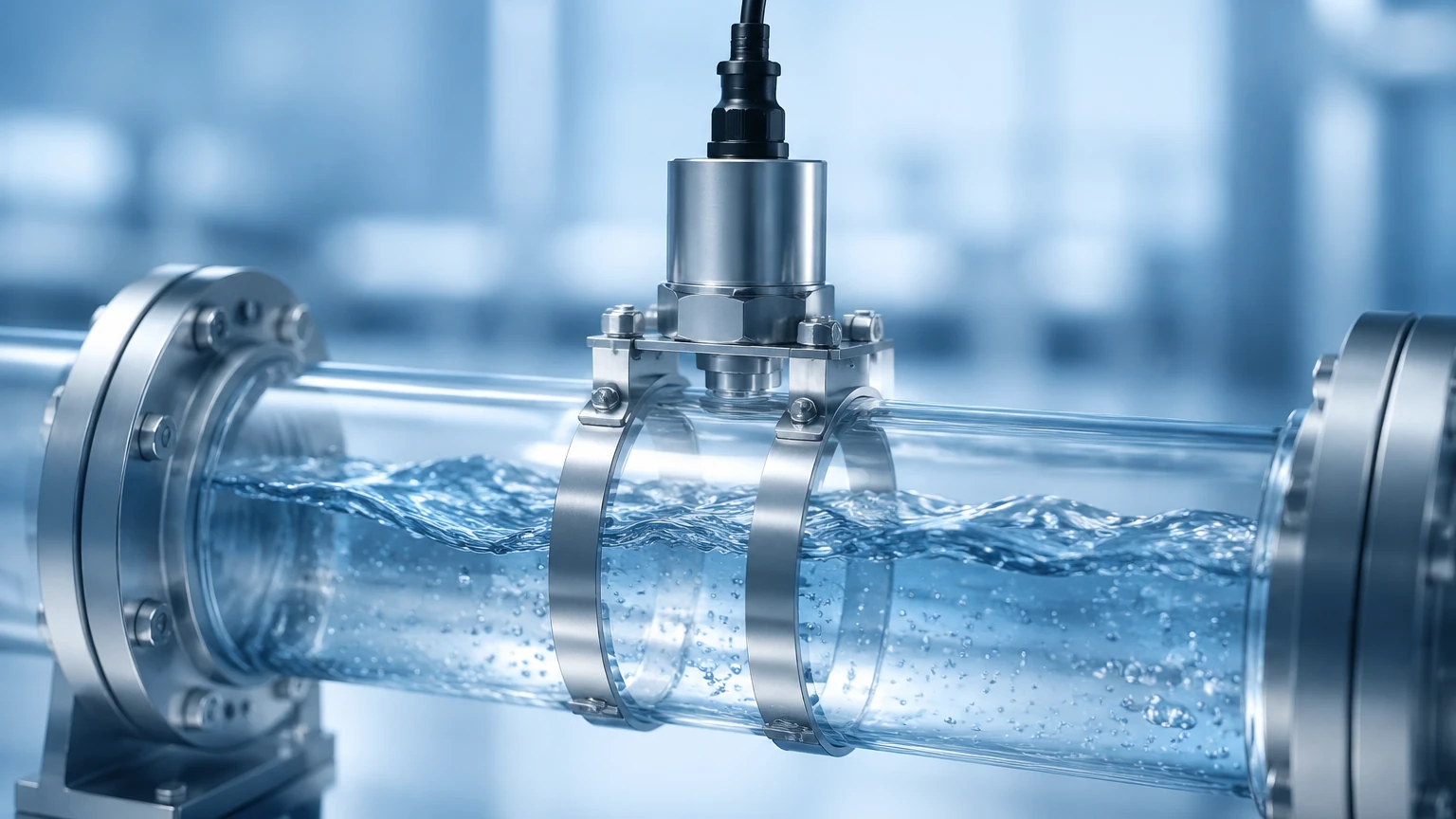
Electromagnetic sensors operate based on Faraday’s Law of Electromagnetic Induction. This law states that a conductor moving through a magnetic field produces an electrical signal. In this application, the conductive liquid acts as the conductor. As the liquid flows through a magnetic field generated by the sensor’s coils, it creates a voltage proportional to the velocity of the flow.
* Requirement: The fluid must be electrically conductive (typically >5 μS/cm).
* Advantage: No moving parts and no pressure drop.
* Common Use: Water treatment and chemical processing.
2. Ultrasonic Flow Meters
Ultrasonic sensors use sound waves to determine flow velocity. There are two primary types:
* Transit-Time: These sensors send ultrasonic pulses back and forth across the pipe. The pulse traveling with the flow moves faster than the one traveling against it. The difference in time is used to calculate the velocity. This is ideal for clean liquids.
* Doppler Effect: These sensors reflect sound waves off particles or bubbles in the fluid. The frequency shift of the reflected wave indicates the flow speed. This is preferred for slurries or aerated liquids.
3. Differential Pressure (DP) Flow Meters
DP meters rely on Bernoulli’s Principle, which describes the relationship between pressure and velocity. By placing a constriction in the pipe (such as an orifice plate, Venturi tube, or nozzle), the sensor creates a pressure drop. The square root of the pressure difference between the upstream and downstream sides is proportional to the flow rate.
4. Vortex Flow Meters
Vortex sensors utilize the phenomenon known as the Karman Vortex Street. When a fluid meets a "bluff body" (an obstruction), it creates alternating vortices. The frequency at which these vortices are shed is directly proportional to the flow velocity. These are highly effective for measuring steam, gases, and low-viscosity liquids.
5. Thermal Mass Flow Meters
These sensors measure the heat dissipation of a heated element placed in the flow stream. As the fluid moves past the sensor, it carries heat away. The amount of energy required to maintain the temperature difference or the rate of cooling provides a direct measurement of mass flow, particularly for gases.
Practical Selection Criteria
Choosing the right flow rate sensors involves evaluating the chemical and physical properties of the process media against the sensor’s technical specifications. The following table provides a quick reference for common industrial technologies.
Flow Sensor Selection Table
| Technology | Suitable Media | Accuracy (Typical) | Pressure Drop | Moving Parts |
| :— | :— | :— | :— | :— |
| Electromagnetic | Conductive Liquids | ±0.5% | None | No |
| Ultrasonic | Clean/Dirty Liquids | ±1.0% | None | No |
| Vortex | Steam, Gas, Liquids | ±1.0% | Low | No |
| Differential Pressure | Clean Liquids/Gases | ±1.0% – 2.0% | Medium/High | No |
| Turbine | Clean, Low-Viscosity | ±0.25% | Medium | Yes |
| Thermal Mass | Gases | ±1.0% | Negligible | No |
| Coriolis | Most Liquids/Gases | ±0.1% | Medium | No |
Technical Considerations for Installation
Even the most advanced flow rate sensors will fail to provide accurate data if installed incorrectly. Engineers must adhere to strict installation protocols to ensure laminar flow and signal integrity.
Straight Pipe Requirements
Most flow sensors require a specific length of straight pipe both upstream and downstream from the installation point. This is necessary to eliminate turbulence caused by elbows, valves, or pumps. A common rule of thumb is "10D Upstream and 5D Downstream," where D is the internal diameter of the pipe. For example, if the pipe diameter is 100 mm, the sensor should have 1,000 mm of straight pipe before it and 500 mm after it.
Orientation and Filling
For liquid applications, the pipe must be completely full to ensure accurate measurement. In horizontal installations, sensors should be placed at a point where the pipe remains flooded. For vertical installations, it is generally recommended that the flow moves upward. This ensures the pipe remains full and prevents air pockets from gathering at the sensor head.
Environmental and Electrical Factors
* Grounding: For electromagnetic meters, proper grounding is essential to prevent electrical noise from interfering with the micro-volt signals generated by the sensor.
* Vibration: Vortex and some ultrasonic meters can be sensitive to mechanical vibrations. Sensors should be installed away from heavy machinery or properly dampened.
* Temperature Compensation: For gas flow, changes in temperature and pressure significantly affect volume. Advanced sensors often include integrated temperature probes to provide compensated mass flow readings.
The Relationship Between Flow and Level
In many industrial scenarios, flow measurement is achieved through level measurement. This is particularly common in open channel flow, such as in wastewater treatment plants or irrigation canals. By using a flume or a weir, the flow of the liquid is restricted in a controlled manner.
According to hydraulic formulas, the height (level) of the liquid at a specific point in the flume is directly related to the flow rate. In these cases, a non-contact ultrasonic level sensor or a radar level meter is used to monitor the head height, and the flow rate is calculated by the transmitter. For organizations looking for integrated solutions, you can Review product options and application support on our Main Page to see how level instruments are applied in flow calculations.
Common Risks and Limitations
While flow rate sensors are robust, they are subject to specific operational risks that can lead to drift or failure:
1. Cavitation: If the pressure in the pipe drops below the vapor pressure of the liquid, bubbles form and collapse. This can damage the sensor lining and cause significant measurement errors.
2. Scaling and Coating: In chemical or wastewater applications, material can build up on the sensor electrodes or inner walls. This is a common issue for electromagnetic meters, though many modern units feature self-cleaning electrodes.
3. Signal Interference: High-frequency drives (VFDs) and other electrical equipment can introduce noise into the sensor cabling. Using shielded cables and maintaining physical separation between power and signal lines is mandatory.
4. Viscosity Changes: Technologies like turbine meters are highly sensitive to changes in fluid viscosity. If the process temperature fluctuates, the resulting change in viscosity can lead to non-linear errors.
Frequently Asked Questions (FAQ)
Q: Can I use an ultrasonic flow meter on a pipe with a liner?
A: Yes, but the liner must be well-bonded to the pipe wall. If there is an air gap between the liner and the pipe, the ultrasonic signal will be reflected and will not reach the fluid.
Q: What is the difference between volumetric flow and mass flow?
A: Volumetric flow measures the space the fluid occupies (e.g., m³/h), whereas mass flow measures the actual weight of the fluid (e.g., kg/h). Mass flow is preferred for gases because their volume changes significantly with temperature and pressure.
Q: How often should flow rate sensors be calibrated?
A: Calibration frequency depends on the criticality of the process and the type of fluid. For most industrial applications, an annual calibration check is standard. However, in regulated industries like pharmaceuticals or food production, more frequent intervals may be required.
Q: Are there flow sensors that can measure bidirectional flow?
A: Yes, electromagnetic and ultrasonic flow meters are naturally capable of measuring flow in both directions, provided the transmitter is configured to handle bidirectional signals.
Conclusion
Flow rate sensors are indispensable tools for maintaining efficiency, safety, and quality in industrial environments. Whether you are managing a simple water distribution system or a complex chemical reactor, the choice of sensor technology must be grounded in the physical realities of the application. By understanding the measurement principles—from electromagnetic induction to ultrasonic transit times—and adhering to strict installation guidelines regarding pipe runs and orientation, engineers can ensure long-term reliability.
For those integrating flow systems with storage and processing tanks, ensuring accurate level measurement is the next logical step in process optimization. To explore professional-grade level measurement instruments that complement your flow control strategy, visit the Welk Main Page for detailed technical specifications and support.