In Line Instrumentation
In Line Instrumentation
In the landscape of modern industrial automation, in line instrumentation serves as the sensory nervous system for process control. These devices, installed directly into piping systems, tanks, and reactors, provide the critical data necessary to maintain safety, optimize yield, and ensure product quality. For engineers and facility managers, selecting the correct in line instrumentation—specifically for level measurement—requires a deep understanding of fluid dynamics, material compatibility, and electronic sensing principles.
Welk, a professional manufacturer of industrial level measurement instruments, specializes in providing robust solutions that withstand the rigors of chemical processing, water treatment, and oil and gas operations. This guide explores the fundamental technologies, selection criteria, and installation best practices for integrating in line level measurement into your industrial infrastructure.
Core Measurement Principles in Level Instrumentation
Before selecting a specific device, it is essential to understand the physics behind the measurement. In line instrumentation for level detection generally falls into two categories: continuous measurement and point level detection. Continuous measurement provides a constant signal (typically 4-20mA or digital bus) representing the exact level, while point level detection acts as a switch to signal high or low states.
Radar Level Measurement (Non-Contact and Guided)
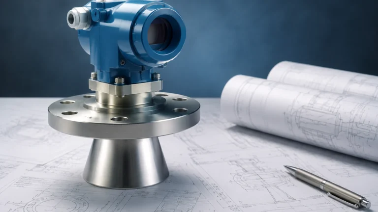
Radar technology utilizes electromagnetic waves to determine the distance to a liquid or solid surface. High-frequency signals (ranging from 26GHz to 80GHz) are emitted from the antenna, reflected by the medium, and received back. The "Time of Flight" (ToF) is calculated to determine the level.
- 80GHz Radar: Offers a narrow beam angle, making it ideal for vessels with internal obstructions like agitators or heating coils. It provides accuracy up to ±2mm (0.078 inches).
- Guided Wave Radar (GWR): Uses a physical probe or cable to guide the microwave signal. This is particularly effective in low dielectric media or applications with heavy foam and turbulence.
Ultrasonic Level Measurement
Ultrasonic sensors emit high-frequency sound pulses. The sensor measures the time it takes for the echo to return after hitting the surface of the medium. Because sound speed is affected by air temperature, Welk ultrasonic sensors include integrated temperature compensation to maintain accuracy. These are cost-effective for water treatment and open-channel flow applications but are limited in vacuum environments or high-pressure steam applications where sound transmission is inconsistent.
Hydrostatic Pressure Measurement
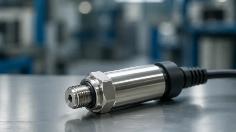
Hydrostatic transmitters measure the pressure exerted by a liquid column. Based on the principle that pressure is proportional to the height of the liquid multiplied by its density ($P = \rho gh$), these sensors are installed at the bottom of a tank or submerged within it. They are highly reliable for vented tanks but require compensation for pressurized vessels.
Magnetic Level Gauges
Magnetic gauges are a form of visual in line instrumentation that uses a float containing a permanent magnet. As the float rises and falls with the liquid level in a bypass chamber, it rotates magnetic flaps or rollers on an external scale. This provides a clear, power-free visual indication, often supplemented with reed switches or transmitters for remote monitoring.
Key Evaluation Criteria for In Line Instrumentation
Selecting the right instrument is not a "one size fits all" process. Engineers must evaluate several environmental and chemical factors to ensure long-term reliability. For a comprehensive overview of available technologies, professionals often consult the Main Page of the Welk technical catalog to compare model specifications.
1. Media Characteristics
- Dielectric Constant (εr): Crucial for radar. Low dielectric fluids (like oils) reflect less energy than high dielectric fluids (like water).
- Viscosity and Coating: High-viscosity fluids can coat probes, leading to false readings in contact-based sensors. In such cases, non-contact radar or ultrasonic sensors are preferred.
- Corrosivity: The wetted parts must be compatible with the process media. Welk offers materials ranging from SS316L to specialized coatings like PTFE, PVDF, and PFA.
2. Process Conditions
- Temperature: Standard sensors may operate up to 80°C (176°F), but high-temperature variants with cooling fins or specialized ceramics can handle up to 250°C (482°F) or higher.
- Pressure: Hydrostatic and magnetic gauges must be rated for the maximum vessel pressure. High-pressure radar systems are available for oil and gas separators operating at 40 bar (580 PSI) or more.
- Turbulence and Foam: Heavy foam can absorb ultrasonic and radar signals. Guided wave radar or hydrostatic sensors are often the solution for these challenging environments.
3. Output and Communication
Modern in line instrumentation must integrate with PLC, DCS, or SCADA systems. Standard outputs include 4-20mA with HART protocol, Modbus RTU, and Profibus. For remote sites, wireless LoRaWAN or NB-IoT options are becoming increasingly common.
Practical Selection Table
| Technology | Best For | Max Accuracy | Pressure Limit | Typical Application |
| :— | :— | :— | :— | :— |
| 80GHz Radar | Precise chemical/solids | ±2mm | Up to 40 bar | Corrosive tanks, silos |
| Ultrasonic | Water/Wastewater | ±0.25% | Atmospheric | Sumps, open channels |
| Hydrostatic | Deep wells/Vented tanks | ±0.1% | N/A (Submersible) | Water towers, fuel tanks |
| Guided Wave Radar | Low dielectric/Foam | ±5mm | Up to 100 bar | Oil/Water separators |
| Magnetic Gauge | Visual monitoring | ±5mm | Up to 160 bar | Boilers, storage tanks |
Installation Considerations and Best Practices
The performance of in line instrumentation is heavily dependent on proper installation. Even the most advanced sensor will fail if placed incorrectly within the process line.
Mechanical Mounting
- Nozzle Height and Diameter: For radar and ultrasonic sensors, the nozzle should be as short as possible. If a nozzle is too long or narrow, the signal may reflect off the nozzle wall (ringing), creating a "dead zone" where the sensor cannot detect the level.
- Avoid Obstructions: Sensors should not be installed directly above ladders, agitator blades, or inflow pipes. If obstructions are unavoidable, many Welk instruments feature "false echo suppression" software to map out and ignore these static reflections.
- Positioning: Sensors should generally be placed at 1/4 to 1/3 of the tank diameter away from the wall to avoid interference from wall effects while staying clear of the center vortex in agitated tanks.
Electrical and Wiring
- Shielding: Use shielded twisted pair cables to prevent EMI (Electromagnetic Interference) from high-power motors or VFDs (Variable Frequency Drives).
- Grounding: Ensure the instrument housing is properly grounded to the vessel or plant ground to prevent static buildup and signal noise.
- Cable Entry: Always use proper cable glands and create a "drip loop" to prevent moisture from entering the housing via the cable.

Limitations and Common Risks
While in line instrumentation has advanced significantly, certain limitations persist. Awareness of these risks allows for better contingency planning.
1. The "Blind Zone" (Dead Band): Every ultrasonic and radar sensor has a minimum distance it cannot measure (usually 100mm to 500mm from the sensor face). If the tank overfills into this zone, the sensor may report an error or a frozen maximum value.
2. Vapor and Condensation: While radar can penetrate most vapors, heavy steam can attenuate ultrasonic signals. Condensation on the sensor face can also cause signal loss; Welk solves this with PTFE-faced antennas that shed droplets easily.
3. Vacuum Effects: Ultrasonic sensors cannot function in a vacuum because sound requires a medium (air/gas) to travel. Radar or hydrostatic sensors must be used instead.
4. Density Shifts: Hydrostatic sensors are sensitive to changes in fluid density. If the temperature changes significantly or the fluid composition varies, the level reading will drift unless a secondary pressure sensor is used for compensation.
Frequently Asked Questions (FAQs)
Q: How often should in line instrumentation be calibrated?
A: For most industrial applications, an annual calibration check is recommended. However, in high-precision chemical dosing or regulated water treatment, semi-annual checks may be required. Many digital instruments now offer self-diagnostic features that alert operators when the signal signal-to-noise ratio degrades.
Q: Can one sensor measure both liquid and foam?
A: Most sensors measure the top of the foam layer or the liquid surface depending on the foam density. Guided wave radar is generally the best at detecting the true liquid level through a layer of light foam.
Q: What is the benefit of 80GHz over 26GHz radar?
A: The 80GHz frequency allows for a much smaller antenna and a narrower beam (as low as 3 degrees). This makes it easier to install in small nozzles and prevents the signal from hitting the tank walls or internal structures.
Q: Are these instruments suitable for hazardous areas?
A: Yes, Welk provides instruments with ATEX, IECEx, and CNEx certifications for use in explosive atmospheres (Zone 0, 1, and 2). Always verify the specific certification requirements of your site before purchase.
Conclusion and Next Steps
Effective in line instrumentation is the foundation of process efficiency and safety. By matching the measurement principle—whether it be the precision of 80GHz radar or the reliability of hydrostatic pressure—to the specific needs of the application, engineers can reduce downtime and maintenance costs.
When planning a new installation or upgrading an existing system, it is vital to confirm the chemical compatibility of wetted parts and the electrical requirements of your control architecture. For technical support, custom OEM/ODM inquiries, or to view our full range of level switches and transmitters, please visit the Main Page of our site. Our engineering team is available to provide detailed application reviews to ensure your instrumentation performs accurately in the most demanding industrial environments.