Inline Pressure Sensor
Inline Pressure Sensor
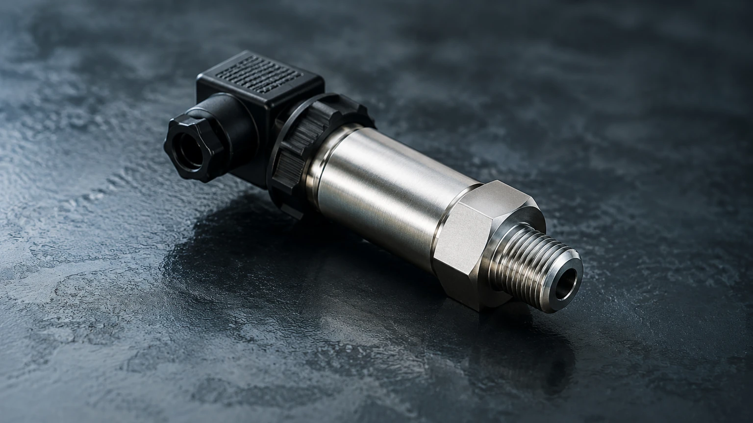
In modern industrial process control, the inline pressure sensor serves as a fundamental component for monitoring, regulating, and securing fluid systems. Unlike remote sensing technologies, an inline pressure sensor is integrated directly into the process piping or vessel wall, providing real-time data on the internal force exerted by liquids or gases. For engineering teams and plant operators, selecting the correct sensor involves a deep understanding of fluid dynamics, material science, and electronic signal processing.
This guide examines the technical principles, selection criteria, and installation requirements for inline pressure sensors, particularly their application within the broader context of level and flow measurement in sectors such as water treatment, chemical processing, and oil and gas.
Understanding Inline Pressure Measurement Principles
Before selecting an instrument, it is essential to understand the physics governing the conversion of physical pressure into an electrical signal. Most industrial inline pressure sensors rely on the displacement of a sensing element—typically a diaphragm—which reacts to the force of the process medium.
Piezoresistive Sensing
This is the most common technology used in industrial applications. A piezoresistive sensor consists of a diaphragm with integrated strain gauges. When pressure is applied, the diaphragm deforms, changing the electrical resistance of the gauges. This change is proportional to the pressure and is converted into a standard output signal (e.g., 4-20mA). Piezoresistive sensors are favored for their high sensitivity and stability across wide pressure ranges.
Capacitive Sensing
Capacitive sensors measure the change in electrical capacitance between a flexible sensing diaphragm and a fixed reference plate. As the process pressure moves the diaphragm, the distance between the plates changes, altering the capacitance. These sensors are exceptionally accurate, especially at very low pressure ranges, and offer high resistance to overpressure conditions.
Ceramic Thick-Film Technology
In highly corrosive environments, ceramic diaphragms are often preferred. These sensors use a thick-film strain gauge fired onto a ceramic base. Because ceramic is chemically inert and extremely hard, these sensors resist abrasion and chemical attack better than standard stainless steel components.
Types of Sensors for Industrial Applications
Inline pressure sensors are categorized based on their reference point. Choosing the wrong reference can lead to significant measurement errors, especially in low-pressure applications.
1. Gauge Pressure Sensors: These measure pressure relative to the local atmospheric pressure. They are vented to the atmosphere and are the standard choice for most tank and pipe applications.
2. Absolute Pressure Sensors: These measure pressure relative to a perfect vacuum. They are used in vacuum distillation, evaporation processes, and applications where atmospheric pressure fluctuations would interfere with the reading.
3. Differential Pressure (DP) Sensors: These measure the difference between two pressure points. While often used for flow measurement across an orifice plate, they are also critical for level measurement in pressurized vessels.
Role in Hydrostatic Level Measurement
While an inline pressure sensor is often viewed as a tool for pipe monitoring, it is a primary technology for hydrostatic level measurement. The principle is based on the fact that the pressure at the bottom of a liquid column is directly proportional to the height of that liquid.
The formula used is:
P = ρ × g × h
* P: Hydrostatic pressure
* ρ (rho): Density of the liquid
* g: Gravitational constant (approx. 9.81 m/s²)
* h: Height of the liquid column
In an open tank, an inline sensor mounted at the bottom measures the gauge pressure, which is converted to a level reading. If the liquid density is constant, this method provides a highly reliable and cost-effective level solution. For those evaluating these systems alongside other technologies like radar or ultrasonic, you can find more details on the Main Page of our technical resource site.
Key Selection Criteria for Engineering Teams
Selecting an inline pressure sensor requires balancing performance requirements with environmental constraints. The following table provides a reference for common material and specification choices.
Selection Reference Table
| Criteria | Options/Ranges | Typical Application |
| :— | :— | :— |
| Diaphragm Material | SS316L, Tantalum, Hastelloy C, Ceramic | SS316L for water; Hastelloy for acids; Ceramic for slurries. |
| Pressure Range | 0–100 mbar to 0–1000 bar | Low range for level; High range for hydraulic systems. |
| Process Temperature | -40°C to +125°C (Standard) | High-temp versions available with cooling fins for steam. |
| Output Signal | 4-20mA, HART, RS485 Modbus | 4-20mA for simplicity; HART for remote diagnostics. |
| Accuracy Class | 0.5%, 0.25%, 0.1% FS | 0.5% for general monitoring; 0.1% for custody transfer. |
Chemical Compatibility
The wetted parts (diaphragm and process connection) must be compatible with the medium. For example, while 316L stainless steel is excellent for water and food products, it may succumb to chloride stress corrosion in certain chemical environments. In such cases, a flush-mount diaphragm with a PTFE coating or a Tantalum diaphragm is necessary.
Installation Best Practices and Considerations
The longevity and accuracy of an inline pressure sensor depend heavily on correct installation. Poor placement can lead to air entrapment, sediment buildup, or excessive thermal stress.
Orientation and Mounting
* Liquid Applications: The sensor should ideally be mounted on the side or bottom of the pipe to ensure the sensing element is always submerged and to prevent air bubbles from interfering with the reading.
* Gas Applications: The sensor should be mounted on the top or side of the pipe to allow any condensate to drain away from the sensor diaphragm.
* Steam Applications: Always use a siphon (pigtail or U-type) to create a water seal that protects the sensor from direct contact with high-temperature steam.
Process Connections
Standard threaded connections (NPT or G threads) are common, but for hygienic applications in the pharmaceutical or food industries, Tri-Clamp or DIN 11851 milk pipe fittings are required to eliminate "dead legs" where bacteria could grow. In heavy industrial settings, flanged connections are preferred for their robustness and ease of maintenance.
Environmental Protection
Industrial sensors are often exposed to wash-downs or outdoor weather. Ensure the sensor housing meets the required Ingress Protection (IP) rating. IP67 is standard for most environments, while IP68 is required for sensors that may be temporarily or permanently submerged.
Limitations and Maintenance Requirements
Despite their versatility, inline pressure sensors have limitations that must be managed through proactive engineering.
1. Temperature Drift: All pressure sensors exhibit some degree of signal drift when temperatures change. High-quality sensors include internal temperature compensation, but extreme fluctuations can still impact accuracy.
2. Clogging: In applications involving slurries or high-viscosity fluids (like wastewater or crude oil), standard recessed diaphragms can clog. A flush-diaphragm design, where the sensing surface is level with the pipe wall, is the recommended solution.
3. Overpressure Events: Pressure spikes (water hammer) can permanently deform a diaphragm. Selecting a sensor with a high overpressure rating (typically 2x to 4x the nominal range) is a critical safety margin.
Maintenance Checklist
* Zero-point Calibration: Periodically check the sensor output at zero pressure to account for long-term drift.
* Diaphragm Inspection: For abrasive media, inspect the diaphragm for pitting or thinning.
* Seal Integrity: Check O-rings and gaskets for signs of degradation, especially in chemical processes.
Frequently Asked Questions (FAQs)
Q: Can an inline pressure sensor be used for flow measurement?
A: Yes, when used in a differential pressure configuration across a primary flow element (like a Venturi tube or orifice plate), the pressure drop can be used to calculate the flow rate.
Q: What is the difference between a flush diaphragm and a recessed diaphragm?
A: A recessed diaphragm is protected inside the sensor body, suitable for clean gases and liquids. A flush diaphragm sits even with the process connection, preventing material buildup, making it ideal for viscous or dirty fluids.
Q: How do I handle pressure measurement in high-vibration environments?
A: Use sensors with potted electronics and robust electrical connectors (like M12 or heavy-duty junction boxes). In extreme cases, remote mounting the sensor using a capillary tube can isolate it from the vibration source.
Q: Is it necessary to use a pressure transmitter or just a sensor?
A: In B2B industrial contexts, the terms are often used interchangeably, but a "transmitter" specifically refers to the sensor combined with electronics that provide a regulated, long-distance signal like 4-20mA or a digital bus.
Conclusion
The inline pressure sensor remains a cornerstone of industrial instrumentation. Whether it is used to monitor pipe integrity or to provide precise hydrostatic level data in a chemical reactor, its performance is dictated by the alignment of sensor technology with the specific demands of the process environment. By prioritizing material compatibility, correct reference pressure, and robust installation techniques, engineers can ensure long-term reliability and process safety.
For further technical specifications and to compare different measurement technologies for your specific project, please refer to the Main Page for detailed product documentation and application support.