Inline Ultrasonic Flow Meter
Inline Ultrasonic Flow Meter
In the landscape of industrial process control, the accurate measurement of liquid flow is as critical as the monitoring of tank levels. The inline ultrasonic flow meter has emerged as a cornerstone technology for facilities requiring high precision, low maintenance, and long-term reliability. Unlike traditional mechanical meters that rely on moving parts—which are prone to wear and pressure drops—ultrasonic technology utilizes acoustic signals to determine volumetric flow rates. This guide provides a comprehensive technical overview of inline ultrasonic flow meters, their operating principles, selection criteria, and installation requirements for engineering professionals.
Understanding the Principles of Inline Ultrasonic Flow Measurement
Before selecting a flow measurement solution, it is essential to understand the physics governing the technology. Inline ultrasonic flow meters primarily operate on the Transit-Time (Time-of-Flight) principle.
The Transit-Time Principle
This method employs a pair of ultrasonic transducers mounted in a spool piece (the "inline" section). These transducers function as both transmitters and receivers. One transducer sends an acoustic signal diagonally across the pipe to the other. When the fluid is stationary, the time taken for the signal to travel upstream and downstream is identical.
When the fluid is moving, the signal traveling in the direction of the flow (downstream) moves faster than the signal traveling against the flow (upstream). The meter measures this minute time difference (delta-t). This difference is directly proportional to the velocity of the fluid. By integrating the velocity with the known cross-sectional area of the pipe, the device calculates the volumetric flow rate with high accuracy.
Doppler Shift Principle
While less common for high-precision inline spool pieces, some ultrasonic meters use the Doppler effect. This involves reflecting ultrasonic signals off particles or air bubbles within the fluid. The frequency shift between the transmitted and received signal indicates the flow velocity. However, for most clean-water and chemical applications, the transit-time method is preferred due to its superior accuracy in clear liquids.
Key Components and Construction of Inline Units
An inline ultrasonic flow meter is distinct from "clamp-on" varieties because the transducers are factory-integrated into a dedicated pipe section, or spool. This construction offers several engineering advantages:
1. Fixed Geometry: The distance between transducers and the path angle are precisely calibrated at the factory, eliminating the signal alignment errors often found in clamp-on installations.
2. Direct Contact or Integrated Windows: Transducers may be in direct contact with the medium or separated by a thin, acoustically transparent window, ensuring maximum signal strength and minimal attenuation.
3. Material Integrity: Spool pieces are typically manufactured from carbon steel, stainless steel (304/316), or specialized alloys to match the existing piping system's pressure and chemical compatibility requirements.
Evaluation Criteria for Industrial Applications
Selecting the correct inline ultrasonic flow meter requires a detailed analysis of the process environment. Engineers should use the following table as a baseline for initial technical evaluation:
| Parameter | Technical Requirement | Note |
| :— | :— | :— |
| Fluid Type | Clean liquids, water, chemicals, oils | Best for fluids with <2% solids/bubbles |
| Pipe Diameter | DN15 (1/2") to DN1000 (40") | Inline units are highly accurate in small diameters |
| Accuracy | ±0.5% to ±1.0% of measured value | Higher precision than most mechanical meters |
| Temperature Range | -30°C to +160°C | High-temp versions available for steam condensate |
| Pressure Rating | 1.6 MPa to 4.0 MPa (Standard) | Depends on flange rating (ANSI/DIN) |
| Output Signals | 4-20mA, Pulse, Modbus RTU, HART | Essential for SCADA/PLC integration |
Fluid Conductivity and Acoustic Properties
Unlike electromagnetic flow meters, which require the fluid to be conductive, ultrasonic meters are independent of conductivity. They can measure deionized water, hydrocarbons, and non-conductive chemicals. However, the fluid must be "sonically conductive," meaning it must allow the passage of high-frequency sound waves without excessive absorption or scattering.
Installation Considerations and Best Practices
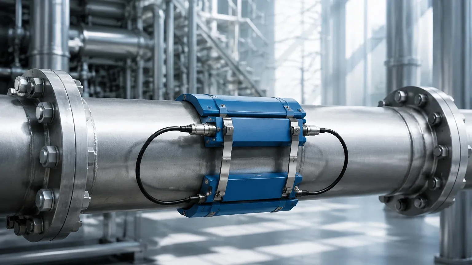
To achieve the stated accuracy of an inline ultrasonic flow meter, strict adherence to installation geometry is required. The flow profile must be fully developed and stable as it passes through the measurement section.
Straight Pipe Run Requirements
The most common cause of measurement error is turbulence caused by upstream obstructions. Engineers should follow the 10D/5D Rule:
* Upstream: A minimum of 10 pipe diameters (10D) of straight, unobstructed pipe before the meter.
* Downstream: A minimum of 5 pipe diameters (5D) of straight pipe after the meter.
* If the meter is placed after a pump or a high-turbulence valve, the upstream requirement may increase to 20D or 30D.
Mounting Orientation
* Horizontal Pipes: The meter should be installed such that the transducers are on the sides of the pipe (3 o'clock and 9 o'clock positions). This prevents air bubbles (which collect at the top) or sediment (which collects at the bottom) from interfering with the acoustic path.
* Vertical Pipes: Flow should always be in the upward direction. This ensures the pipe remains completely full, as any air pockets or partially filled pipes will cause the meter to fail or report significant errors.
Common Risks and Operational Limitations
While highly reliable, the inline ultrasonic flow meter is not a universal solution for every application. Understanding its limitations is key to avoiding project failures.
1. Entrained Air and Solids: High concentrations of bubbles or suspended solids (typically >2-5% by volume) can scatter the ultrasonic signal. If the signal strength drops below a certain threshold, the meter will lose its "lock" on the flow.
2. Scaling and Fouling: Over time, heavy scaling on the internal walls of the spool piece can change the internal diameter and attenuate the signal. Regular inspection is recommended in hard water or heavy chemical applications.
3. Acoustic Short-Circuiting: In some poorly designed units, the ultrasonic signal can travel through the metal pipe wall rather than the fluid. High-quality inline meters use acoustic damping materials or specific geometries to prevent this.
Integrating Flow and Level Measurement in Process Automation
In most industrial water treatment or chemical processing plants, flow measurement is only one half of the equation. Monitoring the volume of fluid in storage tanks or process vessels is equally vital for inventory management and overfill prevention. While ultrasonic technology is excellent for flow, specialized instruments like radar level meters or hydrostatic transmitters are required for vessel monitoring.
For engineers looking to standardize their instrumentation suites, reviewing a broad range of measurement technologies is beneficial. You can Review product options and application support on our Main Page to see how flow data can be integrated with advanced level measurement solutions to create a comprehensive automation strategy. This holistic approach ensures that both the movement and the storage of critical fluids are monitored with consistent accuracy.
Frequently Asked Questions (FAQ)
Q: Does an inline ultrasonic flow meter require periodic recalibration?
A: Because there are no moving parts to wear out, the mechanical calibration of the meter remains stable for years. However, in regulated industries (like pharmaceutical or food grade), annual electronic verification or wet-calibration is often required to maintain compliance.
Q: Can these meters measure flow in both directions?
A: Yes, most transit-time inline ultrasonic flow meters are inherently bi-directional. They can measure flow in both the forward and reverse directions and provide separate totalizers for each, which is particularly useful in loading/unloading applications.
Q: What is the impact of viscosity on measurement accuracy?
A: Ultrasonic meters are sensitive to the Reynolds number, which is affected by viscosity. High-viscosity fluids can change the flow profile from turbulent to laminar. Modern digital flow processors include Reynolds number compensation to maintain accuracy across varying viscosities, but this must be specified during the selection phase.
Q: How does the pressure drop of an inline ultrasonic meter compare to a turbine meter?
A: The pressure drop is significantly lower. Since the inline ultrasonic meter has a full-bore design with no rotors or obstructions in the flow path, the pressure loss is equivalent to a straight length of pipe of the same dimensions.
Conclusion
The inline ultrasonic flow meter represents a sophisticated balance of acoustic physics and digital signal processing. By eliminating moving parts and providing a stable, factory-calibrated measurement environment, these devices offer a low-total-cost-of-ownership solution for modern industry. When combined with proper installation practices and a clear understanding of fluid properties, they provide the precise data necessary for optimized process control and efficiency. For those managing complex tank farms or treatment facilities, integrating these flow solutions with reliable level measurement instruments ensures a complete and fail-safe monitoring system.