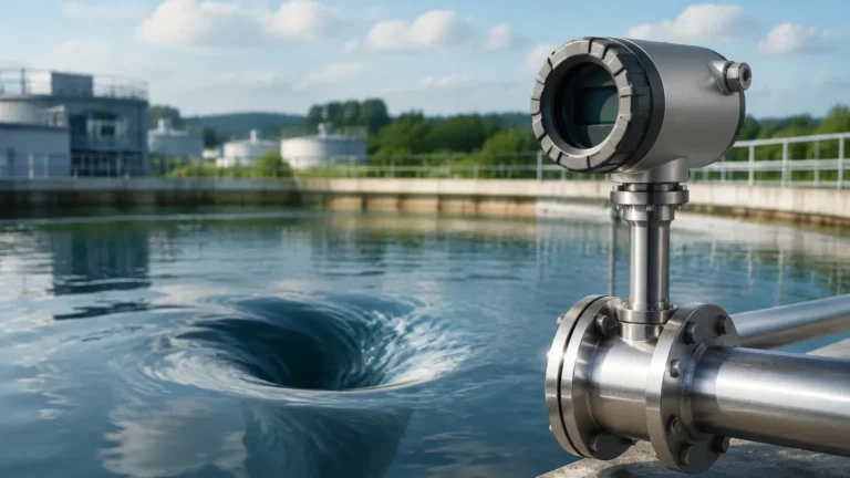
Insertion Mass Flow Meter
Insertion Mass Flow Meter
In industrial process control and facility management, measuring gas flow accurately is essential for energy efficiency, safety, and regulatory compliance. Among the various technologies available, the insertion mass flow meter has emerged as a preferred solution for large-diameter pipes and ducts. Unlike volumetric flow meters that require additional sensors for pressure and temperature compensation, mass flow meters provide direct measurement of the gas mass, which is a more reliable indicator of the actual amount of substance moving through a system.
This guide explores the engineering principles, selection criteria, and installation best practices for insertion mass flow meters within the context of industrial automation and process monitoring. For professionals seeking a comprehensive range of measurement instrumentation, visiting the Main Page of a specialized manufacturer like Welk provides access to technical specifications and application-specific support.
Measurement Principles: Thermal Dispersion
The vast majority of insertion mass flow meters utilize thermal dispersion technology. This principle relies on the fact that gases absorb heat as they flow past a heated surface. The rate of heat absorption is directly proportional to the mass flow rate of the gas.
The Sensor Configuration
An insertion probe typically contains two Resistance Temperature Detectors (RTDs). These sensors are usually constructed from platinum and are protected by a rugged metal sheath (such as 316 Stainless Steel or Hastelloy).
1. The Reference Sensor: This RTD measures the actual temperature of the process gas. It provides a baseline for the electronics to understand the ambient conditions within the pipe.
2. The Active Sensor: This RTD is heated to a specific temperature above the reference sensor.
Constant Temperature Differential Method
In the most common implementation, the electronic transmitter maintains a constant temperature difference (ΔT) between the heated sensor and the reference sensor. As gas flows past the probe, it carries heat away from the active sensor. To maintain the fixed ΔT, the electronics must increase the electrical power supplied to the heated sensor. Because the cooling effect is determined by the number of gas molecules passing by (the mass), the amount of power required is directly related to the mass flow rate. This allows the meter to output a signal (typically 4-20mA or Modbus) that represents the mass flow without needing separate pressure or temperature transmitters.
Why Choose Insertion Over In-Line Meters?
Flow meters are generally available in two form factors: in-line and insertion. An in-line meter consists of a spool piece that is flanged or threaded into the piping system. An insertion meter, conversely, consists of a single probe that is inserted through a hole in the pipe wall.
Cost-Effectiveness in Large Pipes
For small pipes (under 50 mm or 2 inches), in-line meters are often practical. However, as pipe diameters increase to 200 mm, 500 mm, or even several meters, the cost of an in-line meter becomes prohibitive due to the amount of material and the size of the flanges. An insertion mass flow meter uses the same sensor probe regardless of pipe size, making it significantly more cost-effective for large-scale industrial applications.
Ease of Installation and Maintenance
Insertion meters can often be installed via a "hot tap" procedure. This involves welding a reinforced fitting (a threadolet or flanged nozzle) onto the pipe, installing a ball valve, and then drilling through the pipe wall while the system is still pressurized. The probe is then inserted through the valve. This eliminates the need for process shutdowns during installation or maintenance, a critical factor in 24/7 operations like wastewater treatment or chemical processing.
Technical Selection Criteria
Selecting the right insertion mass flow meter requires a detailed understanding of the process environment. Engineers must evaluate several factors to ensure long-term accuracy and reliability.
1. Gas Composition and Calibration
Thermal mass flow meters are gas-specific. Because different gases (e.g., Nitrogen, Carbon Dioxide, Compressed Air, Methane) have different thermal properties (specific heat and thermal conductivity), the meter must be calibrated for the specific gas or gas mixture it will measure. If the gas composition changes significantly over time, the accuracy of the meter will be affected.
2. Flow Range and Turndown Ratio
One of the primary strengths of thermal mass flow technology is its high turndown ratio, often exceeding 100:1. This means the meter can accurately measure both very low leak rates and high-velocity process flows. This is particularly useful in compressed air auditing and flare gas monitoring.
3. Process Temperature and Pressure
Standard insertion probes can typically handle temperatures up to 200°C (392°F) and pressures up to 20 bar (290 psi). For high-temperature applications, such as stack gas monitoring, specialized high-temperature versions are required. It is important to note that while the meter compensates for temperature and pressure to calculate mass flow, the physical components must still be rated for the maximum process conditions.
4. Pipe Material and Size
The electronics require the internal pipe diameter to calculate the total flow rate from the point-velocity measured by the probe. Accurate measurements depend on the user providing the correct pipe schedule and dimensions during setup.
Practical Selection Table
| Application | Typical Gas | Recommended Probe Material | Key Consideration |
| :— | :— | :— | :— |
| Compressed Air Monitoring | Dry Air | 316 Stainless Steel | Low pressure drop; detects leaks |
| Wastewater Aeration | Ambient Air | 316 Stainless Steel | Resistance to moisture/condensation |
| Natural Gas Distribution | Methane (CH4) | 316 SS / ATEX Rated | Explosion-proof housing required |
| Flue Gas Measurement | Combustion Byproducts | Hastelloy / Ceramic Coated | Corrosion and high temperature |
| Nitrogen Blanketing | Pure N2 | 316 Stainless Steel | High sensitivity at low flow |
Installation Considerations and Best Practices
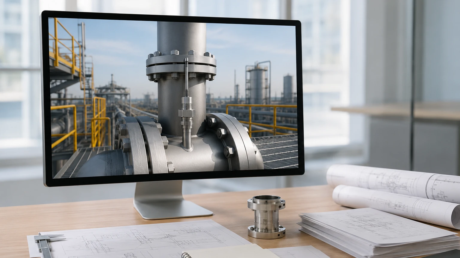
The accuracy of an insertion mass flow meter is heavily dependent on the velocity profile of the gas within the pipe. In a perfect scenario, the gas moves in a laminar fashion, but in reality, elbows, valves, and pumps create turbulence.
Straight Run Requirements
To ensure a stable velocity profile, the probe should be installed in a straight section of pipe. The general rule of thumb is:
* Upstream: 20 pipe diameters (20D) of straight pipe before the meter.
* Downstream: 10 pipe diameters (10D) of straight pipe after the meter.
If these distances are not available, flow conditioners (vane-type or perforated plates) can be used to artificially stabilize the flow, though this may introduce a slight pressure drop.
Insertion Depth
For pipes with a diameter up to 500 mm, the sensor is typically placed at the center of the pipe, where the velocity is highest and most representative. For very large ducts, the probe may need to be inserted to a specific depth (often 1/8th or 1/4th of the diameter) determined by a traverse study to find the average velocity point.
Orientation
In horizontal pipes carrying gases that may contain moisture, the probe should be installed from the side (3 o'clock or 9 o'clock position). This prevents water droplets from pooling on the sensor (if installed at the bottom) or air pockets/sediment issues. If the gas is very dry, top installation (12 o'clock) is often preferred for ease of access.
Limitations and Risks
While highly versatile, insertion mass flow meters are not suitable for every application. Understanding these limitations prevents costly measurement errors.
1. Moisture and Condensation: Thermal mass flow meters measure the cooling effect of the gas. If liquid droplets (water or oil) hit the heated sensor, they cause a sudden, massive cooling effect, which the meter interprets as a massive spike in flow. These meters are best suited for dry gas applications. For wet gases, specialized "clog-resistant" sensors or heated tips may be required.
2. Coating and Contamination: If the process gas contains heavy particulates or sticky substances (like unrefined coke oven gas), a coating can build up on the sensor probe. This coating acts as an insulator, slowing the heat transfer and causing the meter to read lower than the actual flow. Regular cleaning intervals are necessary in dirty environments.
3. Flow Profile Sensitivity: As mentioned, they are point-velocity sensors. If the flow profile is irregular due to poor piping design, the single-point measurement will not accurately represent the total volume passing through the pipe.
Maintenance and Troubleshooting
Maintenance for an insertion mass flow meter is generally minimal due to the lack of moving parts. However, a routine schedule should include:
* Visual Inspection: Check the probe for signs of corrosion or erosion, especially in abrasive gas streams.
* Sensor Cleaning: If the gas is not clean, the probe should be removed (using the ball valve/retractor assembly) and cleaned with an appropriate solvent or soft brush. Do not use abrasive materials that could damage the RTD cladding.
* Zero-Flow Check: Periodically, the flow should be stopped to verify that the meter reads zero. A small offset at zero can indicate electronic drift or sensor contamination.
Frequently Asked Questions (FAQs)
Q: Can an insertion mass flow meter be used for steam?
No. Steam is a phase-change fluid. The moisture content in saturated steam and the high temperatures of superheated steam generally make thermal dispersion technology unsuitable. Vortex or differential pressure meters are better choices for steam.
Q: How often does the meter need recalibration?
In clean gas applications like nitrogen or dry compressed air, many meters can operate for 3 to 5 years without significant drift. In more aggressive environments, an annual calibration check is recommended.
Q: What is the maximum pipe size for an insertion meter?
There is theoretically no upper limit, provided the probe is long enough to reach the required insertion depth and the pipe wall is structurally sound enough to support the mounting. They are commonly used in ducts as large as 5 meters in diameter.
Q: Does the pressure drop matter?
One of the benefits of insertion meters is the negligible pressure drop. Because the probe is very thin relative to the pipe diameter, it does not significantly impede the flow, which saves energy in pumping and compression costs.
Conclusion
The insertion mass flow meter is a robust and economical tool for industrial gas measurement, particularly in large-scale infrastructure. By providing direct mass flow data without the need for auxiliary sensors, it simplifies the instrumentation architecture of modern plants. When integrated into a broader measurement strategy—alongside the level measurement and automation solutions provided by manufacturers like Welk—these meters enable precise control over resources and emissions. For further technical details on integrating these sensors into your specific process, refer to the Main Page for expert guidance and product documentation.