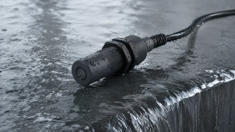
Intrinsically Safe Flow Meter
Intrinsically Safe Flow Meter
In industrial environments where flammable gases, vapors, or combustible dusts are present, the selection of instrumentation is governed by strict safety protocols. An intrinsically safe flow meter is a specialized device designed to operate in these hazardous locations by limiting the electrical and thermal energy to levels below what is required to ignite a specific hazardous atmospheric mixture. Unlike explosion-proof methods that contain an internal explosion, intrinsic safety (IS) prevents the ignition from occurring in the first place.
For process engineers and facility managers, understanding the intersection of flow dynamics and electronic safety standards is critical. This guide explores the underlying measurement principles, the technical requirements of intrinsic safety, and the practical considerations for deploying these instruments in modern B2B industrial applications. For a broader look at compatible instrumentation, you may visit the Main Page of industrial measurement solutions.
Core Measurement Principles for Intrinsically Safe Systems
Before selecting a specific intrinsically safe flow meter, it is essential to understand how different technologies interact with the fluid and the electrical constraints of an IS circuit. Because IS devices must operate on very low power, certain measurement principles are more common than others.
Electromagnetic Flow Measurement
Electromagnetic flow meters, or magmeters, operate based on Faraday’s Law of Electromagnetic Induction. This law states that a conductor (the fluid) moving through a magnetic field generates an electrical voltage proportional to its velocity.
In an IS configuration, the field coils must be energized with minimal current, and the electrodes must be designed to prevent any spark discharge into the process fluid. These meters are ideal for conductive liquids, such as water, acids, and slurries. Since they have no moving parts, they offer low pressure drop and high reliability in hazardous chemical processing zones.
Ultrasonic (Transit-Time) Measurement
Ultrasonic flow meters utilize sound waves to determine fluid velocity. In the transit-time method, transducers send and receive ultrasonic pulses both upstream and downstream. The difference in time taken for the signal to travel between the two points is directly proportional to the flow velocity.
For intrinsically safe applications, ultrasonic meters are often preferred because they can be "clamp-on" (non-intrusive). This eliminates the need to cut into pipes, reducing the risk of leaks in high-pressure or toxic environments. The low power consumption of piezoelectric crystals makes ultrasonic technology highly compatible with IS barriers.
Vortex Shedding Principle
Vortex flow meters are based on the Karman Vortex Street principle. When a fluid passes a bluff body (a non-streamlined object) placed in the flow stream, it creates alternating vortices. The frequency at which these vortices are shed is proportional to the fluid velocity.
In hazardous areas, vortex meters are frequently used for steam and gas measurement. The sensors used to detect the pressure fluctuations of the vortices are typically low-power capacitors or piezoelectric elements, which are easily integrated into intrinsically safe 4-20mA loops.
Turbine and Positive Displacement
Turbine meters use the mechanical energy of the fluid to rotate a rotor. The rotational speed is sensed magnetically or optically. While mechanical, the electronic pickup must be intrinsically safe. Positive displacement (PD) meters, which trap fixed volumes of fluid, also require IS-rated pulse transmitters when used in classified areas to ensure the pulse output does not carry sufficient energy to cause ignition.
Defining Intrinsic Safety (IS) in Flow Instrumentation
Intrinsic safety is a protection technique based on the limitation of electrical energy (voltage and current) and the limitation of stored energy (capacitance and inductance).
The Entity Concept
When specifying an intrinsically safe flow meter, engineers must adhere to the "Entity Concept." This involves matching the parameters of the flow meter (the "field device") with the parameters of the safety barrier (the "associated apparatus"). The key parameters include:
* Vmax (Ui): The maximum voltage the flow meter can receive.
* Imax (Ii): The maximum current the flow meter can receive.
* Pmax (Pi): The maximum power the flow meter can receive.
* Ci and Li: The internal capacitance and inductance of the meter, which must be accounted for when calculating the total energy storage of the circuit.
Comparison with Explosion-Proof (XP) Methods
While explosion-proof housings are designed to withstand and contain an internal explosion, intrinsic safety is often preferred for instrumentation for several reasons:
1. Live Maintenance: IS circuits allow for maintenance and calibration while the equipment is powered, without requiring a "hot work permit."
2. Wiring Requirements: IS wiring often does not require heavy-duty conduit or poured seals, reducing installation costs.
3. Weight: IS instruments are typically lighter as they do not require heavy, cast-metal enclosures.
Key Evaluation Criteria for Industrial Applications
Selecting the right intrinsically safe flow meter requires a balance between process requirements and safety compliance.
1. Hazardous Zone Classification
Identify the specific zone or division where the meter will be installed.
* Zone 0 / Class I Div 1: Areas where ignitable concentrations of flammable gases are present continuously or for long periods.
* Zone 1 / Class I Div 1: Areas where ignitable concentrations are likely to exist under normal operating conditions.
* Zone 2 / Class I Div 2: Areas where ignitable concentrations are unlikely to occur or will exist only for a short time.
2. Fluid Compatibility and Phase
Not all IS meters work with all fluids. For example, electromagnetic meters require a minimum conductivity (usually >5 μS/cm), making them unsuitable for hydrocarbons. Conversely, vortex and ultrasonic meters are excellent for non-conductive oils and gases.
3. Power Constraints
Because IS circuits limit power, the flow meter must be highly efficient. Most IS flow meters are 2-wire, loop-powered devices (4-20mA). If your application requires high-speed data processing or a backlit display, ensure the IS barrier can provide sufficient current (typically limited to 20-30mA).
4. Turn-down Ratio and Accuracy
Industrial B2B applications often require high precision over a wide range of flow rates. Turbine and vortex meters offer good turn-down ratios (up to 20:1 or 30:1), while electromagnetic meters provide superior accuracy (often ±0.5% of rate) for conductive liquids.
Practical Selection Table
The following table provides a quick reference for matching flow technology with common industrial needs in hazardous areas.
| Technology | Typical Accuracy | Fluid Types | Ideal Hazardous Zone | Primary Advantage |
| :— | :— | :— | :— | :— |
| Electromagnetic | ±0.2% to ±0.5% | Conductive Liquids, Slurries | Zone 0, 1, 2 | No pressure drop; handles solids |
| Ultrasonic | ±1.0% to ±2.0% | Clean Liquids, Gases | Zone 1, 2 | Non-intrusive; no process downtime |
| Vortex | ±0.75% to ±1.0% | Steam, Gases, Low Viscosity | Zone 1, 2 | High temperature/pressure capability |
| Turbine | ±0.25% to ±0.5% | Clean, Low Viscosity Liquids | Zone 1, 2 | High precision; fast response |
| Coriolis | ±0.1% | Most Liquids and Gases | Zone 1, 2 | Direct mass flow; high accuracy |
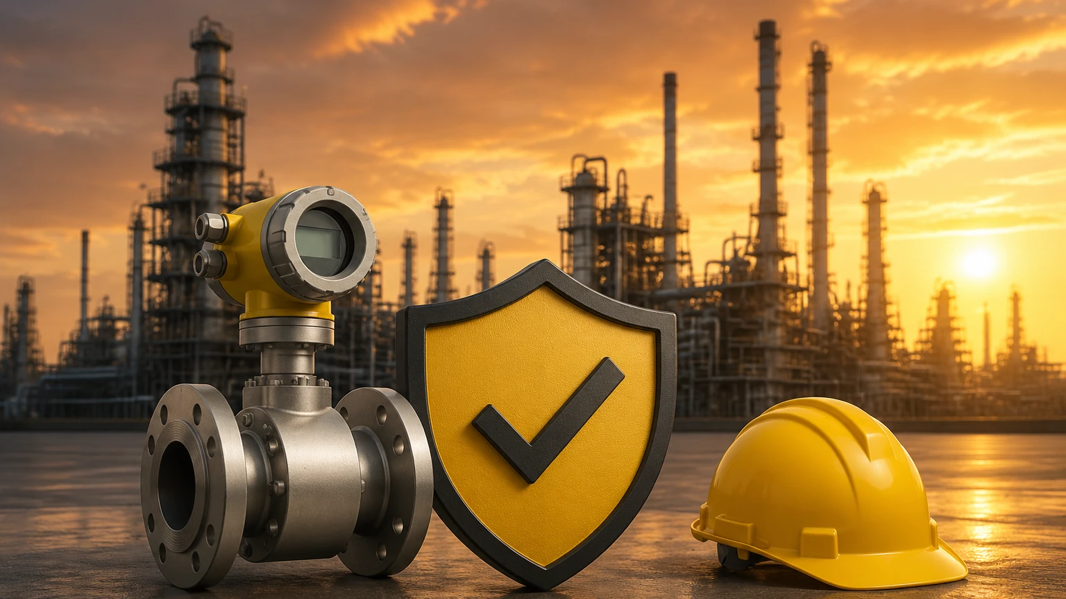
Installation and Wiring Guidelines for IS Circuits
Correct installation is the most critical factor in maintaining the integrity of an intrinsically safe system. Failure to follow these guidelines can negate the safety rating of the entire loop.
Separation of Circuits
IS wiring must be physically separated from non-IS wiring. This is usually achieved by using separate conduits, cable trays, or by maintaining a minimum distance (typically 50 mm or 2 inches) between the two types of circuits. This prevents "fault induction," where a high-voltage surge in a standard power line could jump to the low-power IS line.
Use of Safety Barriers
Every intrinsically safe flow meter must be connected to a safety barrier or galvanic isolator located in a safe area (non-hazardous).
* Zener Barriers: Use resistors and Zener diodes to divert excess energy to the ground. They require a high-quality, dedicated "IS ground."
* Galvanic Isolators: Use transformers or opto-isolators to provide electrical isolation between the hazardous and safe areas. These do not require a dedicated IS ground and are generally more robust against electrical noise.
Grounding and Bonding
In IS systems, proper grounding is essential to ensure that any fault current is safely dissipated. For Zener barrier systems, the ground resistance must typically be less than 1 Ohm. Ensure that the flow meter body is properly bonded to the piping system to prevent static electricity buildup.
Common Risks and Limitations
While an intrinsically safe flow meter provides a high level of protection, there are specific risks and limitations to consider:
* Cable Length and Capacitance: Long cable runs between the barrier and the flow meter add capacitance (Cc) and inductance (Lc) to the circuit. If the total capacitance (Ci + Cc) exceeds the barrier's limit (Co), the system is no longer safe. Always calculate cable parameters for runs exceeding 100 meters (328 feet).
* Low Power Signal-to-Noise Ratio: Because the electrical signals are low-power, they can be susceptible to electromagnetic interference (EMI). Shielded twisted-pair cabling is mandatory.
* Environmental Degradation: In chemical or offshore environments, corrosion can increase the resistance of ground connections or damage seals. Regular inspection of the IS enclosure and barrier terminals is necessary.
* Incompatible Barriers: Using a barrier with a voltage output (Uo) higher than the meter’s input rating (Ui) will cause a safety violation and likely damage the instrument.
Confirming Project Requirements
Before finalizing the purchase of an intrinsically safe flow meter, the engineering team should confirm the following data points:
1. Gas Group: Is the atmosphere Group IIA (Propane), IIB (Ethylene), or IIC (Hydrogen)? IIC requires the strictest energy limitation.
2. Temperature Class: Ensure the device's T-rating (e.g., T4, T6) is appropriate for the auto-ignition temperature of the gases present.
3. Communication Protocol: Does the control system require standard 4-20mA, or is a digital protocol like HART or Modbus (over IS physical layer) required?
4. Certification Body: Does the project require ATEX (Europe), IECEx (International), or UL/CSA (North America) certification?
Conclusion
Deploying an intrinsically safe flow meter is a fundamental requirement for maintaining safety and compliance in hazardous industrial sectors. By selecting a measurement principle that aligns with the fluid properties and ensuring that the electrical loop adheres to the entity concept, operators can achieve accurate flow data without compromising site safety.
Whether you are managing a water treatment facility, a chemical refinery, or an oil and gas platform, the integration of IS-rated instrumentation is an investment in both operational efficiency and risk mitigation. For technical specifications and product comparisons, reviewing the Main Page of reputable manufacturers will provide the necessary data to make an informed engineering decision.