Kaiser Optical Systems
Kaiser Optical Systems
In the landscape of industrial process control, the integration of advanced analytical tools with traditional level measurement is essential for optimizing production efficiency and safety. Kaiser Optical Systems, a brand synonymous with Raman spectroscopy and laser-based analytical instrumentation, represents a specialized segment of optical technology. While traditional level measurement focuses on the physical quantity of a substance within a vessel, optical systems provide deep insights into the chemical composition and molecular structure of those substances.
For engineers and plant managers, understanding how Kaiser Optical Systems and similar spectroscopic technologies interface with level measurement instruments—such as radar level meters, ultrasonic sensors, and hydrostatic transmitters—is key to achieving comprehensive process transparency. This guide explores the principles of optical measurement, its application in industrial environments, and how it complements the robust level measurement solutions found on our Main Page.
Understanding the Principles of Optical Measurement
To appreciate the role of Kaiser Optical Systems in a B2B industrial context, one must first understand the underlying physics of Raman spectroscopy compared to standard level sensing technologies.
Raman Spectroscopy vs. Time-of-Flight (ToF)
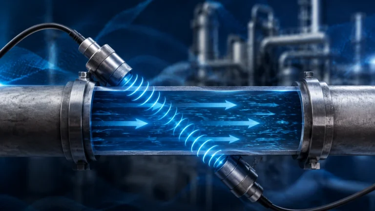
Most industrial level sensors, such as those manufactured by Welk, operate on the Time-of-Flight (ToF) principle. Radar and ultrasonic sensors emit a signal (microwave or sound wave) that reflects off the material surface and returns to the sensor. The distance is calculated based on the time elapsed and the speed of the wave.
In contrast, Kaiser Optical Systems utilize Raman spectroscopy. This involves directing a high-intensity laser beam into a sample. When the light interacts with the molecules of the substance, a small fraction of the light is scattered at different frequencies. This inelastic scattering, known as the Raman effect, provides a "molecular fingerprint" of the substance.
| Feature | Radar/Ultrasonic Level Meters | Raman Optical Systems |
| :— | :— | :— |
| Primary Measurement | Distance / Volume / Level | Chemical Composition / Concentration |
| Medium Interaction | Surface reflection | Molecular vibration/scattering |
| Signal Source | Microwaves or Ultrasonic pulses | Monochromatic Laser (Visible/NIR) |
| Data Output | 4-20mA / HART (Level) | Spectral data (Composition) |
Optical Interface Detection
While Raman systems are primarily analytical, optical principles are frequently used for interface detection. In complex tanks where multiple liquid layers exist (e.g., oil and water), optical sensors can detect the change in refractive index or light absorption, providing a level of detail that standard hydrostatic sensors might miss if the densities are too similar.
Key Evaluation Criteria for Optical and Level Systems
When selecting instrumentation for a facility, engineers must evaluate whether they require physical level tracking, chemical analysis, or both. The following criteria are essential for determining the suitability of optical systems in a process loop.
1. Media Transparency and Turbidity
Optical systems require a clear path for the laser to interact with the media. In highly turbid or opaque liquids, the penetration depth of the laser is limited. Conversely, non-contact radar level meters are largely unaffected by the optical clarity of the liquid, making them superior for measuring levels in dark or muddy substances like crude oil or wastewater.
2. Process Temperature and Pressure
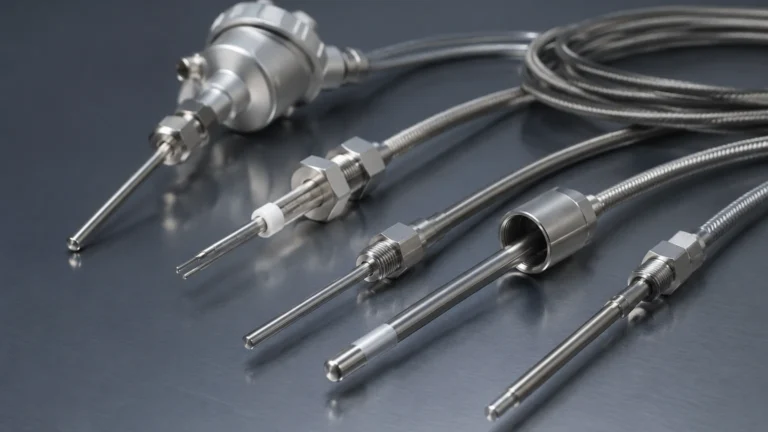
Kaiser Optical Systems often utilize fiber-optic probes to isolate the sensitive spectrometer from harsh process conditions. These probes can be engineered to withstand high temperatures (up to 400°C) and pressures (up to 200 bar / 20 MPa). Similarly, high-frequency radar level meters are designed with PTFE or ceramic seals to handle extreme environments, ensuring that both the analytical and level data remain accurate under stress.
3. Measurement Speed and Real-Time Control
Industrial automation requires low latency. Most level transmitters provide instantaneous readings. Raman systems, depending on the complexity of the molecular structure being analyzed, may require integration times ranging from milliseconds to several seconds. For safety-critical overfill prevention, a dedicated level switch or radar meter is always preferred over an analytical optical system.
Practical Selection Table: Technology Comparison
The following table assists in selecting the appropriate technology based on the specific industrial requirement.
| Application Requirement | Radar Level Meter | Ultrasonic Sensor | Raman Optical System |
| :— | :— | :— | :— |
| Bulk Solid Level | Excellent | Good | Not Applicable |
| Chemical Identification | None | None | Excellent |
| Corrosive Liquids | Excellent (PTFE) | Good (Plastic) | Excellent (Sapphire/Alloy) |
| Foaming Surfaces | Moderate | Poor | Poor |
| Vacuum Conditions | Excellent | Not Applicable | Excellent |
| Interface Level | Good (Guided Wave) | Poor | Excellent (Molecular) |
Installation Considerations for Optical and Level Instrumentation
Proper installation is the deciding factor in the longevity and accuracy of any industrial sensor. Whether installing a Welk radar meter or a Kaiser optical probe, certain engineering standards must be met.
Mounting and Orientation
For level meters, the sensor must be mounted perpendicular to the liquid surface to ensure a strong return signal. For optical probes, the focus point of the laser is critical. Probes are typically installed via a flange or a NPT thread directly into the process piping or the side of a tank.
* Stilling Wells: In agitated tanks, radar and ultrasonic sensors benefit from stilling wells (typically 50mm to 200mm in diameter) to eliminate surface turbulence.
* Optical Windows: If the probe cannot be immersed, an optical window (sight glass) made of fused silica or sapphire is required. This window must be kept clean to prevent signal attenuation.
Cable Management
Kaiser systems rely on fiber-optic cables, which have a minimum bend radius (typically 10x to 20x the cable diameter). Exceeding this radius can cause signal loss or permanent damage to the fiber. Standard level transmitters use shielded twisted-pair cables for 4-20mA signals, which are more robust but still require protection from electromagnetic interference (EMI).
Common Risks and Limitations
Integrating high-end optical systems like those from Kaiser into a process environment involves risks that must be mitigated during the design phase.
1. Fouling and Scaling: The most significant risk for any optical or immersion sensor is the buildup of material on the sensing element. In wastewater or chemical crystallization processes, a thin film can completely block an optical signal. Level meters like the non-contact radar are less susceptible to this, as they can often "see through" minor buildup on the antenna.
2. Laser Safety: Raman systems utilize Class 3B or Class 4 lasers. Proper interlocking and labeling are required to protect maintenance personnel from accidental exposure during sensor removal.
3. Calibration Drift: While Raman systems are remarkably stable, they require periodic validation against known standards. Level meters also require zero-point and span calibration, though the process is generally simpler and can be performed in the field using a reference tape measure.
Information to Confirm Before Implementation
Before proceeding with a purchase or system design, project managers should confirm the following data points with their instrumentation provider:
* Chemical Compatibility: Ensure the wetted parts (316L Stainless Steel, Hastelloy, PTFE, or Sapphire) are resistant to the process media.
* Hazardous Area Ratings: Confirm if the device requires ATEX, IECEx, or FM certification for explosive atmospheres. Many Kaiser systems and Welk level meters are designed for Zone 0/1 environments.
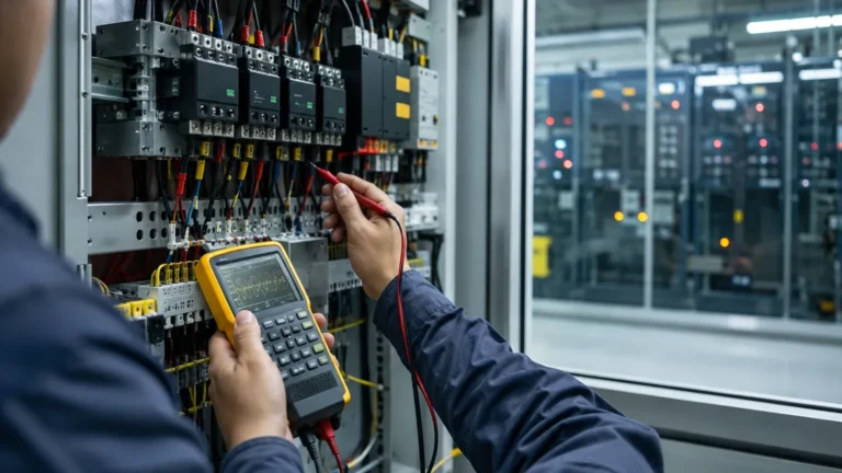
* Integration Protocol: Determine if the system will communicate via 4-20mA, Modbus RTU, Profibus, or Foundation Fieldbus to the existing PLC/DCS.
* Maintenance Access: Ensure there is sufficient clearance (typically 500mm to 1000mm) above the tank or pipe for removing long probes or antennas.
Frequently Asked Questions (FAQs)
Q: Can a Kaiser Raman system replace a level meter?
A: Generally, no. Raman systems are designed for chemical analysis. While they can detect the presence or absence of a liquid at a specific point (acting as a point level switch), they are not cost-effective or designed for continuous level measurement. They are best used in conjunction with a dedicated level transmitter.
Q: How do I handle foam in my tank?
A: Foam is a challenge for both optical and ultrasonic sensors. For heavy foam, a high-frequency radar (80GHz) or a guided wave radar is the most reliable solution. Optical systems will likely scatter the laser light inconsistently in the presence of foam.
Q: What is the typical lifespan of these sensors?
A: With proper maintenance, industrial level meters and optical probes can last 10 to 15 years. The laser source in an optical system may require replacement after 20,000 to 50,000 hours of operation.
Conclusion
Kaiser Optical Systems provide a level of analytical depth that is becoming increasingly important in the era of Industry 4.0. By combining the molecular insights of Raman spectroscopy with the reliable physical measurements provided by radar and ultrasonic level meters, industrial operators can achieve unprecedented control over their processes.
When designing your next measurement loop, consider the synergy between analytical and physical sensing. For a comprehensive range of level measurement instruments tailored to the chemical, water treatment, and oil and gas industries, please visit our Main Page to explore our technical specifications and customized OEM/ODM services.