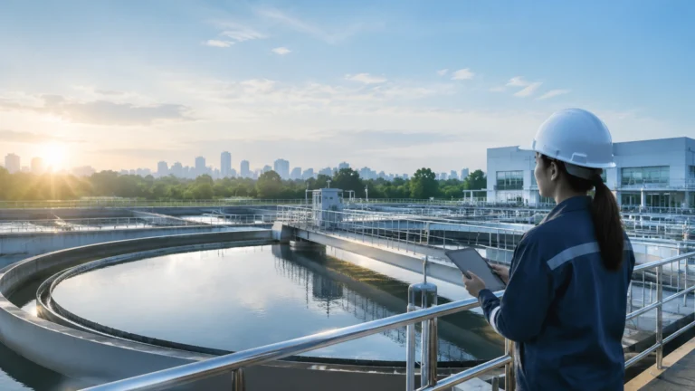
Level Measurement Equipment
Level Measurement Equipment
In the landscape of industrial automation, level measurement equipment serves as a critical component for ensuring process safety, inventory accuracy, and operational efficiency. From water treatment facilities to complex chemical reactors, the ability to monitor the volume or height of liquids and solids within a vessel is fundamental. Selecting the appropriate technology requires a deep understanding of measurement principles, media characteristics, and environmental constraints.
Industrial level measurement is generally categorized into point level detection and continuous level measurement. Point level switches indicate when a substance reaches a specific height, often used for overfill protection or pump control. Continuous level sensors provide real-time data across the entire range of the vessel, allowing for precise inventory management and process control. This guide explores the primary technologies used in modern level measurement equipment and provides engineering benchmarks for selection.
Measurement Principles and Technology Overview
Before selecting a sensor, it is essential to understand the physics behind the most common measurement methods. Each principle offers distinct advantages depending on the physical properties of the media.
Radar Level Measurement (FMCW and Pulse)
Radar level meters operate on the Time-of-Flight (ToF) principle. The sensor emits electromagnetic pulses or a continuous wave that travels to the surface of the material and reflects back to the receiver.
* Non-Contact Radar: These sensors are mounted at the top of the tank and do not touch the media. High-frequency radar, such as 80 GHz, allows for narrow beam angles, which minimizes interference from tank internals like agitators or ladders.
* Guided Wave Radar (GWR): This technology uses a physical probe (rod or cable) to guide the microwave signal. GWR is highly effective for low dielectric constants and applications involving heavy steam or foam, as the probe concentrates the signal energy.
Ultrasonic Level Sensors
Ultrasonic sensors use sound waves rather than electromagnetic waves. The transducer emits an ultrasonic pulse that bounces off the surface of the media. The distance is calculated based on the time it takes for the echo to return. Because sound speed is affected by air temperature, these sensors typically include integrated temperature compensation. They are cost-effective for open-channel flow and atmospheric water tanks but may struggle in vacuum conditions or high-pressure environments where sound cannot propagate effectively.
Hydrostatic Level Transmitters
Hydrostatic measurement relies on the principle that the pressure at the bottom of a liquid column is proportional to the height of the liquid multiplied by its density ($P = \rho gh$). A pressure sensor is placed at the bottom of the tank or submerged in the liquid. This method is highly reliable for vented tanks. In pressurized vessels, a differential pressure (DP) transmitter is required to subtract the head pressure from the total pressure to isolate the liquid level.
Magnetic Level Gauges
Magnetic level gauges are used for visual indication and can be equipped with transmitters for remote monitoring. They consist of a bypass chamber connected to the side of the vessel. A float containing a permanent magnet moves with the liquid level, flipping magnetic flags on an external scale. This provides a clear, power-free visual of the level, which is ideal for high-pressure or high-temperature applications where electronic sensors might face risk.
Key Evaluation Criteria for Selection
Choosing the right level measurement equipment involves more than just matching a sensor to a tank height. Engineers must evaluate the following factors to ensure long-term reliability.
1. Media Properties: Is the substance corrosive, abrasive, or viscous? For corrosive chemicals, non-contact radar or plastic-bodied ultrasonic sensors are preferred. For heavy slurries, hydrostatic sensors with flush diaphragms prevent clogging.
2. Process Conditions: Standard sensors may fail under extreme temperatures (e.g., above 200°C / 392°F) or high pressures (e.g., above 40 bar / 580 psi). Always verify the operating limits of the sensor body and gaskets.
3. Dielectric Constant ($ε_r$): For radar measurement, the reflectivity of the surface depends on the dielectric constant. Materials with low $ε_r$, such as oils or hydrocarbons, reflect less energy than water-based liquids, often necessitating Guided Wave Radar.
4. Tank Geometry: The presence of internal baffles, heating coils, or agitators can create false echoes. Sensors with narrow beam angles or advanced software for "false echo suppression" are required in complex vessels.
Practical Selection Table
The following table provides a comparative overview of common level measurement technologies to assist in preliminary equipment selection.
| Technology | Accuracy | Max Range | Best For | Major Limitation |
| :— | :— | :— | :— | :— |
| 80 GHz Radar | ±1 mm | Up to 120 m | Precise chemical/oil measurement | Higher initial cost |
| Ultrasonic | ±0.25% FS | Up to 15 m | Water/Wastewater, open basins | Affected by foam and vacuum |
| Hydrostatic | ±0.1% to 0.5% | Dependent on Pressure | Submersible applications, deep wells | Sensitive to density changes |
| Guided Wave Radar | ±2 mm | Up to 75 m | Low dielectric liquids, foam | Contact with media is required |
| Level Switch | N/A | Point Level | Overfill protection, pump logic | No continuous data output |
Installation Considerations for Maximum Accuracy
Even the most advanced level measurement equipment will provide inaccurate data if installed incorrectly. Follow these engineering guidelines during the commissioning phase:
* Blocking Distance (Dead Zone): Every sensor has a "dead zone" near the face of the transducer where measurement is impossible. Ensure the maximum liquid level does not enter this zone, or use a nozzle extension to raise the sensor.
* Nozzle Geometry: For radar and ultrasonic sensors, the mounting nozzle should be as short and wide as possible. If the nozzle is too narrow or long, the signal may reflect off the nozzle walls, creating a large interference signal at the top of the range.
* Avoid the Fill Stream: Never install a sensor directly above the point where the tank is filled. The turbulence and the falling stream of material will cause erratic readings and signal loss.
* Orientation: For hydrostatic sensors, ensure the diaphragm is not positioned where sediment can accumulate. For radar, ensure the sensor is mounted perpendicular to the liquid surface to maximize signal return.

Limitations and Common Risks
While modern level measurement equipment is robust, certain environmental factors can compromise performance. Understanding these risks allows for better system design.
* Foam Interference: Heavy, dense foam can absorb ultrasonic and radar signals, leading to a "lost echo" condition. In such cases, Guided Wave Radar or Hydrostatic sensors are more reliable.
* Vapor and Condensation: In closed tanks, condensation can form on the sensor face. While many radar sensors can "see through" light condensation, heavy droplets can cause signal attenuation. Sensors with PTFE-faced antennas are often used to shed moisture.
* Density Fluctuations: Hydrostatic sensors calculate level based on density. If the temperature of the liquid changes significantly, or if different chemicals are mixed, the density changes, and the level reading will drift unless compensated by a PLC or a secondary temperature sensor.
* Dust in Solids Measurement: When measuring silos of grain or cement, dust can attenuate ultrasonic signals. High-frequency radar (80 GHz) is generally the preferred solution for dusty environments due to its ability to penetrate airborne particles.
Frequently Asked Questions (FAQ)
Q: When should I choose Radar over Ultrasonic sensors?
A: Radar is preferred for applications involving vacuum, high pressure, high temperature, or heavy dust/vapor. Ultrasonic is a more cost-effective choice for simple water applications in open tanks or sumps where conditions are stable.
Q: How does the dielectric constant affect my measurement?
A: The dielectric constant ($ε_r$) determines how much energy is reflected back to a radar sensor. Water has a high $ε_r$ (~80) and is easy to measure. Oils have a low $ε_r$ (~2), requiring more sensitive electronics or Guided Wave Radar to ensure a reliable signal.
Q: Do level sensors require regular calibration?
A: Most digital radar and ultrasonic sensors are factory-calibrated and do not drift over time. However, hydrostatic sensors may require periodic zero-point checks to account for sensor aging or changes in atmospheric pressure compensation.
Q: Can I use one sensor for both liquids and solids?
A: Some sensors are versatile, but solids measurement usually requires a higher power output and specialized software to handle the uneven, sloped surface of the material (the angle of repose). Radar sensors with a 80 GHz frequency are currently the most versatile for both media types.
Conclusion
Selecting the right level measurement equipment is a balance between technical requirements and budget constraints. By understanding the underlying physics—whether it is the electromagnetic reflection of radar or the pressure-based calculation of hydrostatic sensors—engineers can design systems that provide years of maintenance-free service. For those looking to implement these solutions, it is helpful to Review product options and application support on the Main Page to find the specific instrument that matches your industrial environment. Proper selection, combined with rigorous installation standards, ensures that level data remains a reliable pillar of your industrial automation strategy.