Electrification Services
Electrification Services
In the modern industrial landscape, the transition from mechanical or manual monitoring to automated, electronic systems is a fundamental component of operational efficiency. Electrification services in the context of level measurement involve the integration of advanced sensors, power management systems, and data communication protocols to replace traditional, labor-intensive methods. For industries such as water treatment, chemical processing, and oil and gas, this shift is not merely a technological upgrade but a strategic necessity to ensure accuracy, safety, and real-time data accessibility.
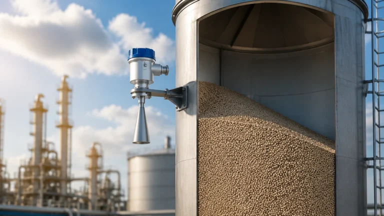
As a professional manufacturer, Welk provides the foundational hardware—radar level meters, ultrasonic sensors, and hydrostatic transmitters—that enables these electrification initiatives. By converting physical levels into standardized electrical signals, facilities can leverage digital ecosystems to optimize resource management and reduce human error.
The Role of Electrification Services in Level Measurement
Electrification services encompass the design, installation, and maintenance of electrical systems that support industrial automation. In level measurement, this refers to the infrastructure required to power sensors and transmit their data to a Central Control Room (CCR) or a Programmable Logic Controller (PLC).
Historically, many plants relied on visual inspection or mechanical float systems. While functional, these methods lack the precision and connectivity required for Industry 4.0. Electrification allows for:
- Remote Monitoring: Eliminating the need for technicians to manually check tanks in hazardous or remote locations.
- Data Logging: Continuous recording of level changes to identify trends and optimize supply chains.
- Automated Alarms: Instant notification of high-level or low-level conditions to prevent overflows or dry-running pumps.
Integrating these services requires a deep understanding of both the physical properties of the medium being measured and the electrical requirements of the instrumentation.
Core Measurement Principles for Electrified Systems
Before implementing electrification services, it is essential to understand the physics behind the sensors. The choice of technology dictates the electrical infrastructure needed, including cabling, power supply (24V DC vs. 220V AC), and signal output (4-20mA, HART, Modbus).
Radar Level Measurement (Non-Contact)
Radar level meters utilize high-frequency electromagnetic waves (typically in the GHz range). The sensor emits a pulse that travels to the surface of the medium, reflects, and returns to the receiver. The "Time of Flight" (ToF) is measured to calculate the distance. Because radar waves do not require a medium for propagation, they are unaffected by vacuum, pressure, or temperature fluctuations, making them ideal for complex chemical environments.
Ultrasonic Level Measurement
Ultrasonic sensors function similarly to radar but use sound waves. The transducer emits an ultrasonic pulse that reflects off the liquid surface. The time taken for the echo to return is proportional to the distance. While cost-effective, ultrasonic waves are sensitive to air temperature changes and surface foam, which can absorb or scatter the sound signal.
Hydrostatic Pressure Measurement
This principle relies on the relationship between the height of a liquid column and the pressure it exerts at the base. A submersible or flange-mounted pressure transmitter measures this force. The formula $P = \rho gh$ (where $P$ is pressure, $\rho$ is density, $g$ is gravity, and $h$ is height) allows the system to calculate the level. This is a contact-based method widely used in water reservoirs and deep wells.
Magnetic Level Gauges and Switches
Magnetic gauges provide a visual indication through a float system but are often "electrified" by adding reed switches or magnetostrictive transmitters. This allows a traditionally mechanical device to provide a continuous electrical output for remote monitoring.
Selecting Level Instruments for Digital Integration
Choosing the right instrument is the most critical step in electrification. Engineers must evaluate the chemical compatibility, process temperature, and the physical layout of the vessel. The following table provides a comparison of common technologies used in electrification projects.
| Technology | Typical Range | Accuracy | Best For | Limitations |
| :— | :— | :— | :— | :— |
| Radar (80GHz) | Up to 120m | ±1mm | Corrosive liquids, solids, high temp | Higher initial cost |
| Ultrasonic | 0.5m – 20m | ±0.25% | Water treatment, open channels | Sensitive to foam and dust |
| Hydrostatic | 1m – 200m | ±0.5% | Deep wells, vented tanks | Requires constant density |
| Level Switches | Point Detection | N/A | Overfill protection | No continuous measurement |
For comprehensive technical specifications and to explore how these instruments fit into your specific infrastructure, you can visit the Main Page for detailed product data sheets.
Technical Implementation and Installation Considerations
The success of electrification services depends on precise installation. Even the most advanced radar meter will fail if the electrical environment is not properly prepared.
Power Supply and Wiring
Most industrial level sensors operate on a 2-wire or 4-wire configuration.
- 2-Wire (Loop Powered): The 4-20mA signal and the power supply share the same pair of wires. This simplifies installation and reduces cabling costs.
- 4-Wire: Power and signal are separated. This is often required for high-power devices like certain radar models or units with integrated displays and heaters.
Signal Interference (EMI/RFI)
In industrial environments, large motors and variable frequency drives (VFDs) generate significant electromagnetic interference. To ensure signal integrity, electrification services must include:
- Shielded Cabling: Using twisted-pair cables with grounded shielding.
- Proper Grounding: Ensuring the instrument and the control cabinet share a common ground to prevent ground loops.
- Signal Isolation: Using isolators to protect the PLC from voltage spikes.
Mounting and Dead Zones
Every sensor has a "dead zone" (blocking distance) near the transducer where measurement is impossible. For example, an ultrasonic sensor might have a 0.3m dead zone. If the tank is filled above this point, the sensor will provide an error or an incorrect reading. Installation must account for the maximum fill level relative to the sensor face.
Challenges and Mitigation in Industrial Electrification
While electrification offers numerous benefits, it introduces specific risks that must be managed during the engineering phase.
1. Hazardous Areas (ATEX/IECEx): In oil and gas or chemical plants, the presence of explosive gases requires intrinsically safe (IS) or explosion-proof (Ex d) equipment. Electrification services must ensure that the energy entering the hazardous zone is limited to prevent ignition.
2. Environmental Factors: Condensation on a sensor face can interfere with ultrasonic and radar signals. Selecting sensors with PTFE-coated antennas or drip shields can mitigate this.
3. Power Stability: Fluctuations in the plant's power grid can cause sensor drift or hardware failure. Implementing surge protection and regulated power supplies is a standard requirement for reliable electrification.
Practical Evaluation Criteria for Project Managers
Before proceeding with an electrification project, stakeholders should confirm the following details with their service provider or equipment manufacturer:
- Media Characteristics: Is the liquid corrosive, viscous, or prone to agitation?
- Vessel Geometry: Are there internal obstructions like agitators, ladders, or heating coils that could cause false echoes?
- Integration Requirements: Does the existing control system support HART, Modbus RTU, or Profibus, or is a simple analog 4-20mA signal sufficient?
- Maintenance Access: Is the sensor mounted in a location where it can be safely calibrated or replaced without shutting down the entire process?
Frequently Asked Questions
Q: Can I electrify an existing mechanical level gauge?
A: Yes. Many magnetic level gauges can be retrofitted with reed switches or magnetostrictive transmitters. This allows you to keep the local visual indication while adding a 4-20mA output for the control room.
Q: What is the benefit of 80GHz radar over 26GHz radar in electrification?
A: 80GHz radar has a much narrower beam angle. This makes it easier to install in tanks with internal obstructions, as the signal is less likely to hit the walls or agitators, resulting in a cleaner signal and easier commissioning.
Q: How does electrification improve safety?
A: By using automated level switches and continuous transmitters, you can implement redundant "High-High" level alarms that automatically shut off inlet pumps, significantly reducing the risk of environmental spills or tank ruptures.
Q: Is wireless electrification a viable option?
A: WirelessHART and ISA100.11a are increasingly common for remote locations where trenching for cables is too expensive. However, these systems require careful battery management and a clear line-of-sight for the wireless gateways.
Conclusion
Electrification services represent a critical bridge between physical industrial processes and digital management. By selecting the appropriate measurement principle—whether it be the precision of radar or the robustness of hydrostatic pressure—and adhering to strict installation standards, facilities can achieve unprecedented levels of accuracy and safety. Welk continues to support these global electrification efforts by providing high-quality instrumentation designed for the rigors of industrial automation. For those seeking to upgrade their current systems, reviewing the technical capabilities of modern sensors is the first step toward a more efficient, electrified future.