Level Pump
Level Pump
In industrial fluid management, the term "level pump" refers to the integrated system where level measurement instrumentation and pumping hardware work in tandem to maintain specific fluid heights, manage drainage, or control process flows. This synergy is critical across various sectors, including wastewater treatment, chemical processing, and industrial automation. For engineers and facility managers, selecting the correct level measurement technology is the first step in ensuring that the pump operates efficiently, avoids dry-running, and prevents overfill conditions.
Effective pump control relies on accurate data. Without a reliable level sensor, a pump may cycle too frequently, leading to premature motor failure, or fail to activate when needed, resulting in costly overflows. This guide examines the principles of level measurement as they apply to pump control, provides selection criteria for different environments, and outlines best practices for system integration.
Measurement Principles for Pump Control
Before selecting a controller or a pump, it is essential to understand the physics behind the level measurement technologies that trigger pump actions. Most level pump systems utilize one of four primary measurement principles.
Ultrasonic Level Measurement
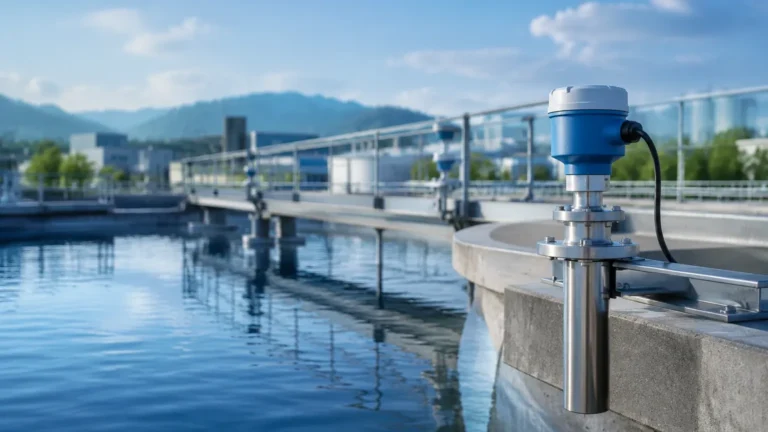
Ultrasonic sensors are among the most common choices for pump control in water and wastewater applications. These devices emit high-frequency sound pulses that travel to the liquid surface and reflect back to the transducer. The sensor calculates the distance based on the time-of-flight of the sound wave.
* Advantages: Non-contact measurement, no moving parts, and relatively low cost.
* Application in Pumping: Ideal for wet wells and sumps where the liquid might be corrosive or contain solids that would foul a contact-based sensor.
Radar Level Measurement
Radar sensors, particularly those operating at high frequencies like 80GHz, use electromagnetic waves instead of sound. These waves travel at the speed of light and are reflected by the dielectric constant of the medium.
* Advantages: Unaffected by temperature fluctuations, vacuum, high pressure, or heavy steam/vapor. Radar provides higher precision than ultrasonic sensors in turbulent conditions.
* Application in Pumping: Preferred for chemical storage tanks or high-temperature process vessels where accuracy is paramount and environmental conditions are volatile.
Hydrostatic Pressure Measurement
Hydrostatic level transmitters measure the pressure exerted by the liquid column above the sensor. Since pressure is directly proportional to the height of the liquid (based on its specific gravity), the level can be calculated accurately.
* Advantages: Highly reliable for deep wells, reservoirs, and vented tanks. They are often submersible, making them easy to install in existing infrastructure.
* Application in Pumping: Commonly used in groundwater monitoring and deep-lift pump stations where top-down mounting of non-contact sensors is impractical.
Point Level Switches (Float and Conductivity)
While continuous measurement is often preferred, many level pump systems use point level switches for basic start/stop logic. Float switches move with the liquid level to mechanically open or close a circuit, while conductivity probes detect the presence of liquid between two electrodes.
* Advantages: Simple, robust, and inexpensive.
* Application in Pumping: Often used as redundant "high-high" or "low-low" alarms to provide a fail-safe backup to continuous sensors.
Integrating Level Sensors with Pump Logic
A level pump system is only as effective as the logic governing its operation. The data from the level sensor is typically sent to a PLC (Programmable Logic Controller) or a dedicated pump controller to execute specific tasks.
1. Simple On/Off Control (Hysteresis)
This is the most basic form of control. The pump is programmed to turn on at a "High" setpoint and turn off at a "Low" setpoint (for emptying applications) or vice versa (for filling applications). This gap, known as hysteresis, prevents the pump from "chattering" or cycling rapidly when the liquid surface is turbulent.
2. Variable Frequency Drive (VFD) Integration
In more sophisticated systems, the level sensor provides a continuous 4-20mA or Modbus signal to a VFD. Instead of simply turning the pump on or off, the VFD adjusts the pump motor speed to maintain a constant level. This reduces energy consumption and minimizes water hammer in the piping system.
3. Lead-Lag Sequencing
In stations with multiple pumps, the level sensor helps manage pump wear. If the level continues to rise despite the "Lead" pump running, the controller activates the "Lag" pump. The system usually alternates which pump is the lead to ensure even wear across the fleet.
Selection Criteria for Level Pump Systems
Choosing the right equipment requires a thorough evaluation of the process media and the physical environment. Use the following table as a baseline for technology selection:
| Feature | Ultrasonic | Radar (80GHz) | Hydrostatic | Float Switch |
| :— | :— | :— | :— | :— |
| Contact Type | Non-contact | Non-contact | Contact (Submerged) | Contact |
| Accuracy | ±0.25% of range | ±1mm to ±2mm | ±0.1% to ±0.5% | N/A (Point only) |
| Media Type | Water, Wastewater | Chemicals, Oils, Solids | Clean Water, Sludge | Most Liquids |
| Foam Tolerance | Poor | Moderate to Good | Excellent | Good |
| Max Range | Up to 15m (typical) | Up to 120m | Up to 200m+ | Limited by cable |
| Cost | Moderate | Higher | Moderate | Low |
When evaluating hardware, engineers should also consult the Main Page of reputable manufacturers to ensure the selected instrument meets the specific hazardous area certifications (such as ATEX or IECEx) required for the site.
Installation Considerations and Best Practices
Proper installation is the difference between a system that runs for years and one that requires weekly maintenance. When setting up a level pump configuration, consider the following:
1. Avoid the Inflow Stream: Never mount a level sensor directly above the pipe where liquid enters the tank. The turbulence and air entrainment will cause false readings and erratic pump behavior.
2. Dead Zones (Blocking Distance): Every non-contact sensor has a "dead zone" directly beneath the transducer where it cannot measure. Ensure the sensor is mounted high enough that the maximum liquid level never enters this zone.
3. Stilling Wells: In highly turbulent tanks, installing the sensor inside a stilling well (a vertical pipe with vent holes) can provide a calm surface for more accurate measurement.
4. Cable Protection: For hydrostatic sensors, ensure the vented cable is protected from moisture entry. A blocked vent tube will result in errors due to changes in atmospheric pressure.
5. Mounting Angle: Radar and ultrasonic sensors must be mounted perpendicular to the liquid surface. Even a few degrees of tilt can significantly reduce the signal strength returned to the sensor.
Limitations and Common Risks
While modern instrumentation is highly advanced, certain environmental factors can still pose risks to a level pump system:
* Build-up and Fouling: In wastewater applications, grease and solids can build up on contact sensors or the faces of ultrasonic transducers. Regular cleaning schedules are necessary to prevent signal loss.
* Vapor and Condensation: While radar handles vapor well, ultrasonic sensors can struggle if heavy condensation forms on the transducer face. Some sensors feature a "dripping" shape or heated faces to mitigate this.
* Signal Interference: Internal tank structures like ladders, agitators, or braces can create "false echoes." Modern sensors use software algorithms to "map out" these obstructions, but careful placement is still the best defense.
* Dry Running: If a level sensor fails in the "on" position, the pump may continue to run after the tank is empty. This can destroy pump seals and impellers within minutes. Always implement a secondary low-level cutoff, such as a simple mechanical float switch.
Frequently Asked Questions (FAQ)
Q: Can I use one sensor to control multiple pumps?
A: Yes. Most modern level controllers can take a single 4-20mA input from a radar or ultrasonic sensor and use it to trigger multiple relay outputs for different pump start/stop setpoints.
Q: How often should I calibrate my level pump sensor?
A: For non-contact sensors like radar, factory calibration is often sufficient for the life of the device, though a yearly check against a manual tape measure is recommended. Hydrostatic sensors may require more frequent zero-point checks due to sensor drift over time.
Q: What is the best sensor for a pump station with heavy foam?
A: Hydrostatic pressure sensors are unaffected by foam because they measure the weight of the liquid. If non-contact is required, high-frequency radar is generally better at penetrating foam than ultrasonic technology.
Q: How do I prevent lightning damage to my sensors in outdoor sumps?
A: Use sensors with built-in surge protection and ensure the system is properly grounded. For long cable runs, external surge arrestors should be installed at both the sensor and the controller end.
Conclusion
Designing a reliable level pump system requires a balance between robust measurement technology and intelligent control logic. By understanding the strengths and limitations of ultrasonic, radar, and hydrostatic sensors, engineers can select a solution that minimizes downtime and maximizes the lifespan of their pumping assets. Whether managing a simple sump or a complex chemical process, the integration of high-quality level instrumentation is the foundation of operational success. For those beginning a new project or upgrading an existing facility, it is helpful to review product options and application support to ensure all technical requirements are met.