Resistive Fuel Level Sensor
Resistive Fuel Level Sensor
In the landscape of industrial fluid management, the resistive fuel level sensor remains one of the most widely utilized technologies for monitoring fuel levels in storage tanks, standby generators, and heavy machinery. While newer technologies such as guided wave radar and ultrasonic sensors have gained traction in high-end process automation, the resistive sensor offers a balance of simplicity, reliability, and cost-effectiveness that is difficult to match in standard fuel monitoring applications. This article provides a comprehensive technical overview of resistive fuel level sensors, their operating principles, selection criteria, and practical installation guidance for engineering professionals.
Measurement Principles of Resistive Sensors
At its core, a resistive fuel level sensor operates on the principle of variable resistance within an electrical circuit. The sensor translates the mechanical position of a float into a specific electrical resistance value, which is then interpreted by a gauge, a controller, or a Telematics Gateway. There are two primary mechanical configurations used to achieve this: the float-arm potentiometer and the vertical reed switch array.
The Potentiometer Principle (Float-Arm)
In a float-arm configuration, a buoyant float is attached to a metal rod (the arm). As the fuel level rises or falls, the arm moves an electrical wiper across a resistive element, typically a wire-wound resistor or a thick-film ceramic substrate. This movement changes the length of the resistive path, thereby altering the total resistance of the circuit. This is essentially a voltage divider or a simple rheostat setup. The output is a continuous analog signal, though it is susceptible to mechanical wear over millions of cycles.
The Magnetic Reed Switch Principle (Vertical Tube)
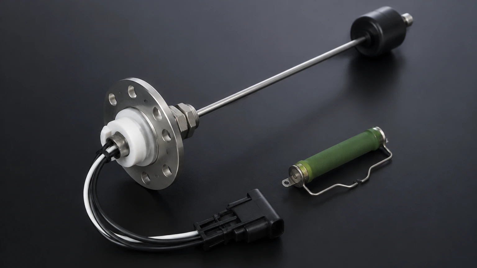
Modern industrial resistive sensors often utilize a vertical tube design. Inside the tube is a series of reed switches paired with fixed resistors. A magnetic float slides up and down the exterior of the tube. As the magnet passes each reed switch, it closes the circuit at that specific point, engaging a specific sequence of resistors. This changes the total resistance in discrete steps. While technically a "stepped" output, the resolution is often high enough (typically 10mm to 21mm intervals) for most industrial fuel monitoring requirements. This design is highly favored in B2B applications because the electrical components are hermetically sealed within the tube, protecting them from fuel-borne contaminants and oxidation.
Technical Specifications and Standards
When specifying a resistive fuel level sensor, understanding the standard resistance ranges is critical for compatibility with existing monitoring equipment. Resistance standards vary by region and application type.
| Standard | Empty Resistance (Ω) | Full Resistance (Ω) | Common Region/Application |
| :— | :— | :— | :— |
| American Standard | 240 Ω | 33 Ω | North America, Marine, Generators |
| European Standard | 10 Ω | 180 Ω | Europe, Industrial Equipment |
| Custom / Industrial | 0 Ω | 90 Ω | Specialized Automotive/Heavy Duty |
| Reverse European | 180 Ω | 10 Ω | Specialized Industrial Control |
Selecting the wrong resistance range will result in inverted readings or a complete failure of the gauge to display data. Most industrial systems now utilize 0-190Ω or 240-33Ω as the default configurations.
Key Evaluation Criteria for Industrial Selection
For procurement and engineering teams, selecting a resistive fuel level sensor requires more than just matching the resistance range. The following factors must be evaluated to ensure long-term reliability in harsh industrial environments.
1. Material Compatibility
Fuel types vary significantly in their chemical aggressiveness. While standard diesel is relatively stable, biodiesel blends and ethanol-blended gasolines can degrade certain plastics and elastomers.
- Sensor Body: 304 or 316L stainless steel is the industry standard for corrosion resistance.
- Float Material: NBR (Nitrile Butadiene Rubber) is commonly used for diesel and oil, while stainless steel floats are preferred for high-temperature or highly corrosive chemical fuels.
2. Resolution and Accuracy
In a reed-switch-based resistive sensor, the resolution is determined by the spacing between the switches. For a tank that is 500mm deep, a 10mm resolution provides 50 data points, which is generally sufficient for inventory management. However, for precise fuel consumption auditing, a higher resolution or a different technology might be required. For those seeking the highest precision in complex industrial environments, you can Review product options and application support on our Main Page to compare resistive options with high-accuracy radar transmitters.
3. Tank Geometry and Depth
The length of the sensor must be carefully matched to the tank depth. A sensor that is too short will leave a large "dead zone" at the bottom of the tank, preventing the detection of low-fuel states. Conversely, a sensor that is too long will bottom out and likely sustain mechanical damage during installation or operation.
Practical Selection Table
| Feature | Float-Arm Sensor | Vertical Reed-Switch Sensor |
| :— | :— | :— |
| Durability | Moderate (Mechanical wear on wiper) | High (Sealed components) |
| Vibration Resistance | Low (Arm can bounce/bend) | High (Stable vertical movement) |
| Installation Space | Requires wide swing radius | Compact vertical footprint |
| Maintenance | May require cleaning of contacts | Virtually maintenance-free |
| Best Use Case | Shallow, wide tanks | Deep, narrow, or high-vibration tanks |
Installation Considerations and Best Practices
Proper installation is paramount to the accuracy of a resistive fuel level sensor. Even the highest quality sensor will provide erratic data if installed incorrectly.
Positioning
The sensor should ideally be located in the center of the tank. This minimizes the impact of "sloshing" or fuel movement when the equipment is in motion or if the tank is not perfectly level. If the sensor is placed at one end of a long rectangular tank, a slight tilt in the equipment will result in a significant error in the reported fuel level.
Mounting Interfaces
Most industrial resistive sensors use one of three standard mounting interfaces:
1. SAE 5-Bolt Pattern: The most common standard for fuel tanks, utilizing a circular flange with five offset holes to ensure the sensor can only be installed in one orientation.
2. NPT/BSP Threaded: Common for stationary storage tanks where the sensor screws directly into a bung (e.g., 1.25" or 1.5" NPT).
3. Bayonet Mount: Often used in automotive and specific OEM machinery for quick-lock installation.
Wiring and Grounding
Resistive sensors are sensitive to electrical noise and grounding issues. In a two-wire system, one wire carries the signal to the gauge, and the other is connected to the common ground. It is essential to ensure a low-resistance ground path. In mobile equipment, the tank itself is often used as the ground, but for plastic tanks, a dedicated ground wire must be run back to the battery or the control panel's common bus bar.
Limitations and Common Risks
While resistive fuel level sensors are robust, they are not without limitations. Engineering teams should be aware of the following risks:
1. Mechanical Wear: In float-arm models, the constant movement of the wiper over the resistive element will eventually wear through the material, leading to "dead spots" where the gauge drops to zero or jumps to full unexpectedly.
2. Fuel Oxidation and Varnish: In tanks where fuel sits for long periods (such as backup generators), fuel can oxidize and form a varnish-like coating on the sensor components. This can cause the float to stick or insulate the electrical contacts in potentiometer models.
3. Sloshing and Signal Noise: Without electronic dampening (either in the sensor head or the receiving gauge), the resistance value will fluctuate rapidly as fuel moves. This can be mitigated by using a sensor with a built-in dampening tube or by implementing software-based averaging in the PLC.
4. Limited Fluid Types: Resistive sensors are designed for non-conductive fluids like fuels and oils. They are generally not suitable for water-based liquids or conductive chemicals, which can short out the resistive element if it is not perfectly sealed.
Maintenance and Troubleshooting Guidance
To troubleshoot a suspected faulty resistive fuel level sensor, a digital multimeter is the primary tool required.
1. Resistance Testing: Disconnect the sensor from the wiring harness. Set the multimeter to the Ohms (Ω) setting and measure across the two sensor leads. Manually move the float from the bottom to the top. The resistance should change smoothly according to the sensor's rated range (e.g., 10Ω to 180Ω). If the reading stays at "OL" (Open Line) or 0Ω, the internal circuit is likely broken.
2. Float Inspection: Remove the sensor and check if the float has become "fuel-logged." If a float develops a microscopic leak, it will fill with fuel and sink, causing the sensor to always report an empty tank.
3. Cleaning: For vertical tube sensors, ensure there is no debris or sludge buildup between the float and the tube that could prevent free movement.
Frequently Asked Questions (FAQ)
Q: Can I use a resistive fuel level sensor for water tanks?
A: It is not recommended unless the sensor is specifically designed for water. Standard fuel sensors often use NBR floats which may degrade, and the internal components may not be sufficiently protected against the corrosive nature of water and dissolved minerals.
Q: How do I convert a resistive signal to a 4-20mA signal for a PLC?
A: You will need a resistance-to-current signal conditioner. These modules take the variable Ohms input and convert it to a standard industrial 4-20mA or 0-10V signal. Some high-end resistive sensors have this electronics package integrated into the head.
Q: What is the maximum depth a resistive sensor can measure?
A: Most vertical reed-switch sensors are available in lengths up to 2000mm. Beyond this depth, the mechanical stability of the tube becomes a concern, and technologies like hydrostatic pressure or radar are usually preferred.
Conclusion
The resistive fuel level sensor remains a cornerstone of industrial level measurement due to its straightforward integration and proven track record. By understanding the nuances of resistance standards, material compatibility, and mechanical configurations, engineers can specify solutions that provide years of reliable service. For applications that exceed the capabilities of resistive technology—such as those requiring non-contact measurement or extreme precision—further exploration of advanced instrumentation is recommended. For more information on the full range of level measurement technologies, including radar and ultrasonic systems, please visit our Main Page.