Optical Level Switch
Optical Level Switch
In the field of industrial automation and fluid management, the optical level switch represents one of the most compact and reliable methods for point-level detection. Unlike traditional mechanical float switches that rely on moving parts, optical sensors utilize the physics of light refraction to determine the presence or absence of a liquid at a specific height. This article provides a comprehensive engineering guide to understanding the principles, selection criteria, and installation requirements for optical level switches in industrial environments.
Measurement Principles of Optical Level Switches
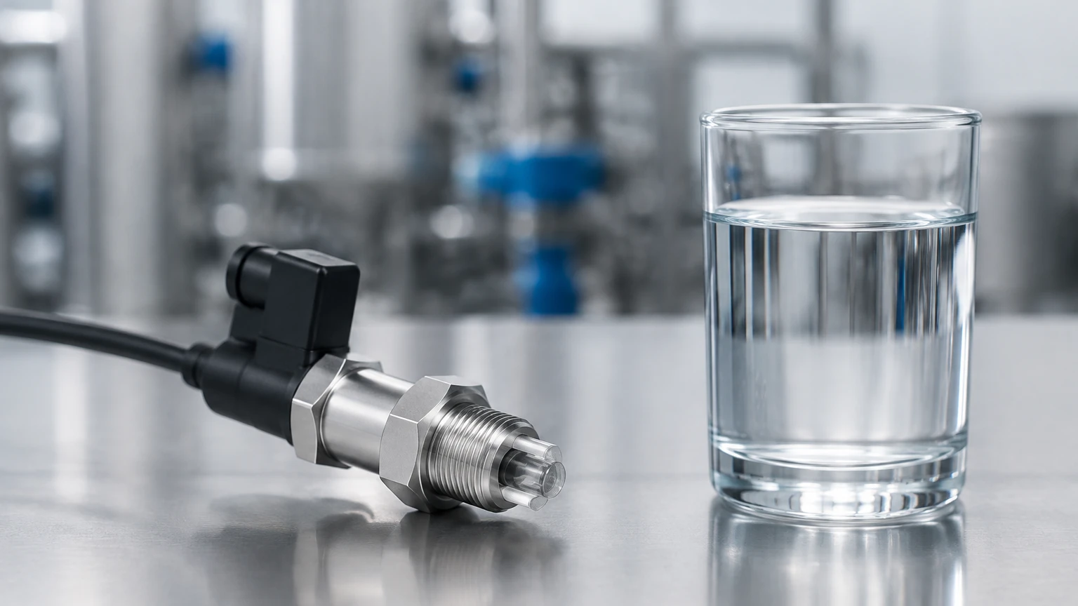
The operation of an optical level switch is based on the principles of total internal reflection and light refraction. The device typically consists of two primary internal components: an infrared Light Emitting Diode (LED) and a phototransistor (receiver), both housed within a transparent plastic or glass sensing tip, often shaped as a prism.
The Dry State (Reflection)
When the sensor tip is surrounded by air or gas, the infrared light emitted by the LED is reflected internally within the prism. Because the refractive index of the prism material is significantly higher than that of air, the light bounces off the internal surface and returns to the phototransistor. The receiver detects this high level of light intensity and outputs a signal indicating a "dry" state.
The Wet State (Refraction)
When the liquid level rises and submerges the sensing tip, the environment surrounding the prism changes from air to liquid. Most liquids have a refractive index much closer to that of the prism material than air does. Consequently, the infrared light is no longer reflected internally; instead, it refracts (escapes) out into the liquid. The phototransistor detects a significant drop in light intensity or a total loss of signal, triggering the switch to change its output state to "wet."
This transition happens almost instantaneously, making optical level switches ideal for high-speed applications or environments where rapid level changes occur.
Key Evaluation and Selection Criteria
Selecting the correct optical level switch requires a detailed analysis of the process media and the environmental conditions of the application. Engineers should evaluate the following parameters to ensure long-term reliability.
1. Material Compatibility
The sensing tip is the only part of the instrument in direct contact with the process media. Common materials include:
* Polysulfone (PSU): A high-performance thermoplastic suitable for most water-based liquids and many chemicals. It is cost-effective but may degrade in the presence of certain solvents or high-strength acids.
* Trogamid: Often used for fuel and oil applications.
* Glass and Stainless Steel: For high-pressure or high-temperature environments, a glass prism fused into a stainless steel housing is the standard choice. This combination offers superior chemical resistance and mechanical durability.
2. Electrical Output Requirements
Optical level switches are available with various output configurations to interface with Programmable Logic Controllers (PLCs) or direct loads:
* NPN or PNP Transistor: Standard for digital integration with industrial control systems.
* Relay Output: Used for switching higher current loads directly, such as small pumps or alarms.
* Voltage/Current: Determining whether the system requires a "Normally Open" (NO) or "Normally Closed" (NC) logic based on fail-safe requirements.
3. Process Conditions
Engineers must confirm the maximum operating pressure and temperature. While plastic-bodied sensors may be limited to 10 bar (145 psi) and 80°C (176°F), high-end industrial models can withstand up to 45 bar (652 psi) and temperatures exceeding 125°C (257°F).
Technical Selection Table
The following table summarizes typical specifications for common optical level switch configurations used in industrial automation.
| Feature | Standard Plastic Sensor | Heavy-Duty Stainless Steel |
| :— | :— | :— |
| Housing Material | Polysulfone / Polycarbonate | Stainless Steel 316L / Glass |
| Max Pressure | 10 bar (145 psi) | 45 bar (652 psi) |
| Temperature Range | -20°C to +80°C | -40°C to +125°C |
| Input Voltage | 5V – 24V DC | 12V – 36V DC |
| Output Type | NPN / PNP / TTL | NPN / PNP / Relay |
| Mounting Thread | M12, 1/4" NPT/G | 1/2" NPT/G, 3/4" NPT/G |
| Typical Accuracy | ±1 mm | ±0.5 mm |
For detailed product specifications and a full range of industrial measurement solutions, technical teams can refer to the Main Page of the manufacturer’s catalog.
Installation Considerations and Best Practices
Correct installation is critical to preventing false triggers and ensuring the longevity of the optical level switch. Because the sensor relies on light, external environmental factors can interfere with its performance.
Orientation and Positioning
* Horizontal Mounting: This is the most common orientation. The sensor should be installed such that the prism tip is positioned at the exact point where the level needs to be detected. Ensure that the sensor is not placed in a "dead zone" where liquid might pool around the tip even after the level has dropped.
* Vertical Mounting: If mounted from the top of a tank, the sensor can detect the high-limit level. If mounted from the bottom, it acts as a low-level or dry-run protection switch. When mounting vertically from the top, ensure the probe length is sufficient to reach the target detection point.
Avoiding Interference
* Reflective Surfaces: If the sensor is installed too close to a reflective tank wall (especially polished stainless steel), the infrared light may reflect off the wall and back into the receiver, causing the sensor to remain in the "dry" state even when submerged. A minimum clearance of 20 mm from any reflective surface is generally recommended.
* Ambient Light: While most modern optical switches use modulated infrared light to ignore ambient sources, extremely bright direct sunlight or high-intensity halogen lamps can occasionally cause interference. Using a protective shroud or orienting the sensor away from direct light sources can mitigate this risk.
* Bubbles and Foam: Small bubbles usually do not affect the switch, but heavy aeration or thick foam can cause the light to refract prematurely or unpredictably. In applications with significant foaming, a stilling well or a different technology, such as a magnetic level gauge, may be more appropriate.
Limitations and Common Risks
While the optical level switch is a versatile tool, it is not a universal solution for every liquid. Engineers should be aware of the following limitations:
1. Coating and Buildup: If the process liquid is highly viscous or prone to crystallization (e.g., heavy syrups, wastewater with high solids), a film may form over the prism. If this film is thick enough to prevent light from escaping, the sensor may stay in the "wet" state regardless of the actual liquid level. Regular cleaning or the use of specialized coatings can help, but for extremely dirty media, ultrasonic or hydrostatic sensors are often preferred.
2. Highly Reflective Liquids: Some specific liquids with very high reflectivity or specific chemical compositions might interfere with the refraction process, though this is rare in standard industrial fluids.
3. Vibration: While optical switches are solid-state and resist vibration better than mechanical switches, extreme mechanical stress can damage the internal electronics or the housing seals over time.
Practical Applications in Industry
Optical level switches are found in a wide variety of B2B and industrial contexts due to their small footprint and reliability:
* Leak Detection: Placed in the secondary containment trays of chemical tanks or under industrial equipment to detect the presence of leaked fluids immediately.
* HVAC Systems: Monitoring condensate levels in drain pans to prevent overflow.
* Hydraulic Reservoirs: Ensuring that hydraulic oil levels remain within safe operating limits for heavy machinery.
* Medical and Laboratory Equipment: Precise level control in small reagent bottles or waste containers where space is extremely limited.
* Food and Beverage: Detecting the presence of water or cleaning solutions in piping systems during CIP (Clean-In-Place) cycles.
Frequently Asked Questions (FAQ)
Q: Can an optical level switch detect the interface between two liquids, such as oil and water?
A: Generally, no. Most optical switches are designed to detect the transition from air to liquid. Because both oil and water cause light to refract away from the prism, the switch will typically register "wet" for both. Interface detection usually requires capacitive or radar-based technologies.
Q: Is the sensor affected by the color of the liquid?
A: In most cases, the color of the liquid does not matter. Whether the liquid is clear, opaque, or dyed, the change in refractive index at the prism surface is usually sufficient to trigger the switch. However, extremely dark or light-absorbing liquids may occasionally require sensitivity adjustments in specialized models.
Q: How do I maintain an optical level switch?
A: Maintenance is minimal since there are no moving parts. The primary requirement is ensuring the sensing tip remains clean. In applications where scaling or film buildup occurs, the tip should be wiped periodically with a soft cloth and a compatible solvent.
Q: What happens if the LED fails?
A: High-quality industrial optical switches are designed with fail-safe logic. In many configurations, if the LED fails or the power is lost, the output will default to a state that indicates a fault or a "high level" to prevent tank overflows (depending on the chosen wiring logic).
Conclusion
The optical level switch is a robust, cost-effective, and highly accurate solution for point-level monitoring in modern industrial processes. By understanding the refractive principles and carefully matching material specifications to the process media, engineers can implement a maintenance-free level control strategy. For those seeking to integrate these sensors into larger automation frameworks, reviewing the comprehensive technical resources available on the Main Page is the recommended next step for ensuring system compatibility and performance.