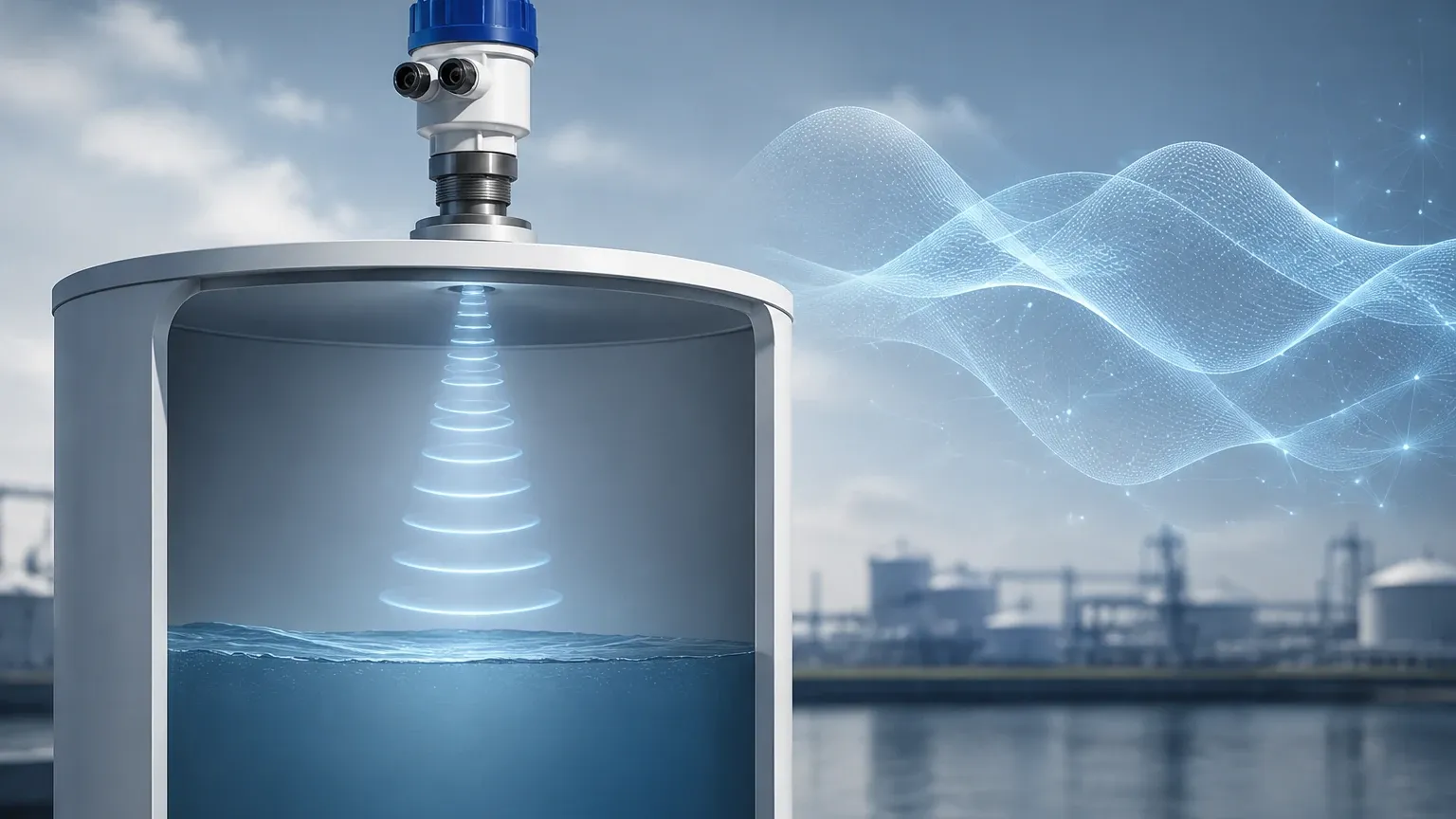
Level Transmitter Ultrasonic
Level Transmitter Ultrasonic
In the landscape of industrial process automation, the level transmitter ultrasonic has established itself as a cornerstone technology for non-contact liquid and solid level measurement. Utilizing high-frequency sound waves to determine the distance to a medium, these instruments provide a balance of accuracy, reliability, and cost-effectiveness. As industries move toward more automated and precise monitoring, understanding the engineering principles, selection criteria, and installation nuances of ultrasonic technology is essential for ensuring operational efficiency.
Understanding the Ultrasonic Measurement Principle
The fundamental operation of a level transmitter ultrasonic is based on the "Time-of-Flight" (ToF) principle. The device features a transducer that contains one or more piezoelectric crystals. When energized, these crystals vibrate at a specific frequency, emitting a pulse of ultrasonic sound waves—typically ranging from 20 kHz to 80 kHz, which is well above the range of human hearing.
These sound waves travel through the air or vapor space in a vessel until they strike the surface of the target material (liquid or solid). Upon impact, a portion of the sound energy is reflected back toward the transducer. The transducer then switches to a receiving mode to detect the returning echo. The transmitter’s internal electronics measure the precise time interval between the emission of the pulse and the reception of the echo.
The distance ($D$) from the sensor face to the material surface is calculated using the following formula:
$$D = \frac{c \times t}{2}$$
Where:
* $c$ is the speed of sound in the medium (usually air).
* $t$ is the total time elapsed for the round trip.
Because the speed of sound is significantly influenced by the temperature of the air through which it travels, most professional-grade level transmitter ultrasonic units, such as those manufactured by Welk, include an integrated temperature sensor. This allows the device to perform real-time temperature compensation, ensuring that the distance calculation remains accurate even as ambient conditions fluctuate. For an in-depth look at various measurement technologies, engineers can visit the Main Page of our technical resource center.
Core Components of an Ultrasonic Level System
A standard industrial ultrasonic level transmitter consists of three primary elements, each critical to the integrity of the measurement signal:
1. The Transducer: Often referred to as the "heart" of the instrument, the transducer converts electrical energy into mechanical sound pulses and vice versa. The material of the transducer face (e.g., PVDF, PTFE, or UPVC) must be chosen based on the chemical compatibility of the stored medium.
2. The Electronic Module: This component handles signal processing. Modern units utilize sophisticated algorithms to filter out "noise" or false echoes caused by internal tank obstructions like ladders, agitators, or weld seams. This process is often called "echo mapping" or "false echo suppression."
3. The Housing: Industrial transmitters are typically housed in robust enclosures rated IP67 or IP68 to protect the electronics from moisture, dust, and corrosive atmospheres. In hazardous environments, explosion-proof or intrinsically safe housings are required.
Key Selection Criteria for Industrial Applications
Selecting the correct level transmitter ultrasonic requires a detailed analysis of the process environment. Unlike contact methods, ultrasonic sensors are sensitive to the atmosphere between the sensor and the product. The following table provides a quick reference for common selection parameters:
| Parameter | Requirement/Impact | Technical Note |
| :— | :— | :— |
| Measurement Range | 0.1m to 30m (Typical) | Higher frequency sensors have shorter ranges but higher resolution. |
| Media State | Liquid, Slurry, or Granular Solid | Solids require higher power due to sound absorption by uneven surfaces. |
| Process Temperature | Standard: -40°C to +80°C | High-temperature versions are available but limited compared to radar. |
| Process Pressure | Near Atmospheric (0.3 MPa max) | High pressure changes air density, significantly affecting sound speed. |
| Chemical Compatibility | Corrosive vs. Non-corrosive | Use PVDF or PTFE-faced transducers for acids and bases. |
| Mounting Connection | Threaded (G/NPT) or Flanged | Ensure the nozzle height does not interfere with the beam angle. |
Installation Guidelines and Best Practices
The performance of a level transmitter ultrasonic is heavily dependent on its physical placement. Even the most advanced signal processing cannot compensate for a fundamentally poor installation. Engineers should adhere to the following guidelines:
1. The Blocking Distance (Dead Zone)
Every ultrasonic sensor has a "blocking distance" or "dead zone" immediately below the transducer face (typically 0.1m to 0.6m depending on the frequency). In this zone, the transducer is still vibrating from the initial pulse and cannot accurately detect a returning echo. The maximum expected liquid level must always remain below this dead zone to avoid signal loss or erratic readings.
2. Beam Angle and Obstructions
The ultrasonic pulse spreads out in a conical shape, usually with a beam angle between 5° and 12°. It is critical to ensure that no internal tank structures—such as cooling coils, ladders, or inflow pipes—intersect this cone. If the beam hits an obstruction, it will create a false echo that may be interpreted as the actual level.
3. Orientation and Positioning
* Perpendicularity: The sensor face must be mounted perfectly parallel to the liquid surface. A tilt of even a few degrees can cause the reflected signal to miss the transducer entirely, especially in low-dielectric or turbulent liquids.
* Wall Distance: Avoid mounting the sensor too close to the tank wall. Echoes from the wall can interfere with the primary signal. A common rule of thumb is to maintain a distance from the wall equal to at least 1/10th of the total tank height.
* Inflow Avoidance: Never mount the sensor directly above the filling inlet. The falling stream of liquid will scatter the ultrasonic pulse and create massive signal noise.
Environmental Factors and Technical Limitations
While the level transmitter ultrasonic is highly versatile, it is not a "one-size-fits-all" solution. Certain environmental conditions can attenuate or distort the sound signal:
* Foam and Turbulence: Heavy surface foam acts as an acoustic insulator, absorbing the ultrasonic pulse rather than reflecting it. In cases of light foam, a higher-power sensor may work, but for thick protein-based foams, radar or hydrostatic transmitters are often preferred.
* Vacuum Conditions: Sound waves require a medium (gas/air) to travel. Therefore, ultrasonic transmitters cannot function in a vacuum.
* Vapor and Dust: Dense dust (in silos) or heavy steam/vapors can change the medium density or scatter the signal. While modern signal processing can handle moderate dust, extreme conditions may require a specialized low-frequency transducer.
* Temperature Gradients: Significant temperature variations between the liquid surface and the sensor can create "layering" in the air, which refracts the sound waves and leads to measurement errors.
Maintenance and Troubleshooting Procedures
One of the primary benefits of the level transmitter ultrasonic is that it has no moving parts, which significantly reduces maintenance requirements. However, periodic checks are recommended to ensure long-term accuracy:
* Transducer Cleaning: In applications involving condensation or splashing, the transducer face may accumulate buildup. A gentle wipe with a soft cloth and mild detergent (if chemically compatible) is usually sufficient. Avoid using abrasive tools that could scratch the piezoelectric surface.
* Signal Strength Monitoring: Most modern transmitters provide a "Signal-to-Noise Ratio" (SNR) or "Echo Quality" metric. A declining SNR often indicates that the transducer face is dirty or that the process conditions (like foam) have changed.
* Troubleshooting "Loss of Echo": If the device displays a "Loss of Echo" (LOE) error, check for:
1. Liquid level entering the dead zone.
2. Extreme turbulence or foam.
3. Misalignment of the sensor face.
4. Heavy condensation or ice on the transducer.
Comparison: Ultrasonic vs. Other Technologies
When evaluating a level transmitter ultrasonic against other technologies, consider the following trade-offs:
* Vs. Radar (GWR or Non-contact): Radar uses electromagnetic waves, which are unaffected by vacuum, dust, or temperature. However, ultrasonic is generally more cost-effective for standard water and chemical applications under 15 meters.
* Vs. Hydrostatic: Hydrostatic sensors are submerged and measure pressure. They are excellent for deep wells but are contact-based and can be affected by changes in liquid density. Ultrasonic remains outside the medium, making it ideal for corrosive or sticky liquids.
Frequently Asked Questions (FAQ)
Q: Can I use an ultrasonic transmitter to measure the level of solids?
A: Yes, but with caveats. Solids like grain, sand, or plastic pellets have an "angle of repose" and tend to absorb sound. You must select a transmitter specifically rated for solids, which usually features higher power and specialized software to handle uneven reflections.
Q: How does wind affect an ultrasonic level measurement?
A: In outdoor applications, such as open-channel flow measurement or reservoir monitoring, strong winds can "blow" the sound pulse away from the transducer, leading to signal loss. Using a stilling well or a sunshade/windshield can help mitigate this.
Q: Is it possible to shorten the dead zone?
A: The dead zone is a physical limitation of the transducer's vibration frequency. To reduce the dead zone, you must use a higher-frequency sensor, which will typically have a shorter overall measurement range.
Conclusion
The level transmitter ultrasonic remains a premier choice for B2B industrial applications due to its non-contact nature and ease of integration into existing control systems. By understanding the physical limitations of sound travel and adhering to rigorous installation standards, engineers can achieve highly accurate level monitoring in water treatment, chemical processing, and food production. For those seeking specific product specifications or customized OEM/ODM solutions, we invite you to Review product options and application support to find the ideal instrumentation for your project requirements. Proper selection today ensures reduced downtime and optimized process safety for years to come.