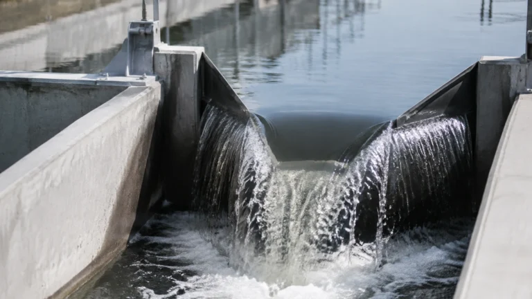
Liquid Level Measurement Lab
Liquid Level Measurement Lab
In both academic research and industrial process development, the liquid level measurement lab serves as a critical environment for validating sensor accuracy, characterizing fluid behavior, and testing the limits of measurement technologies. Precise level control is fundamental to chemical processing, pharmaceutical manufacturing, and water treatment. Understanding the physics behind various sensing methods allows engineers to transition from a controlled lab setting to robust industrial applications.
This guide explores the primary technologies used in level measurement, providing the technical foundation required for selecting, installing, and maintaining instruments in various process conditions. For more information on specific hardware configurations, engineers can visit the Main Page to review comprehensive product options.
Principles of Level Measurement Technology
Before selecting a sensor for a liquid level measurement lab or an industrial facility, it is essential to understand the underlying physical principles. Measurement technologies are generally categorized into non-contact and contact methods.
Radar Level Measurement (ToF)
Radar level meters utilize Time-of-Flight (ToF) technology. The instrument emits high-frequency electromagnetic waves (typically in the 26 GHz or 80 GHz range) toward the liquid surface. These waves are reflected by the media and received by the antenna. The distance is calculated based on the time interval between emission and reception.
* 80 GHz Radar: Offers a narrower beam angle, which is ideal for small lab vessels or tanks with internal obstructions like agitators or heating coils.
* 26 GHz Radar: Often used in larger industrial tanks where dust or steam might be present, providing a reliable signal even in turbulent conditions.
Ultrasonic Level Sensors
Similar to radar, ultrasonic sensors use the ToF principle but rely on sound waves rather than electromagnetic waves. A transducer emits an ultrasonic pulse that bounces off the liquid surface. The sensor measures the time it takes for the echo to return.
Because sound speed is affected by air temperature, most high-quality ultrasonic sensors include an integrated temperature sensor to perform real-time compensation. However, because they rely on a medium (air) to transmit sound, they cannot be used in vacuum applications.
Hydrostatic Level Transmitters
Hydrostatic measurement is based on the principle that the pressure at the bottom of a liquid column is directly proportional to the height of the liquid and its density. The formula used is $P = \rho \cdot g \cdot h$, where:
* $P$ = Pressure
* $\rho$ = Density of the liquid
* $g$ = Gravitational acceleration
* $h$ = Height of the liquid
In a liquid level measurement lab, hydrostatic sensors are often used to demonstrate the relationship between pressure and depth. In industry, they are favored for their simplicity and reliability in vented or open tanks.
Magnetic Level Gauges
Magnetic level gauges utilize a float containing a permanent magnet. As the liquid level rises and falls, the float moves accordingly within a bypass chamber. This movement is tracked by external magnetic flags or a transmitter. This method provides a clear visual indication and is highly effective for high-pressure or high-temperature environments where electronic sensors might face thermal limitations.
Practical Selection Criteria
Choosing the right instrument requires an evaluation of the liquid's properties and the physical constraints of the vessel. The following table provides a comparison of common technologies used in both laboratory and industrial settings.
Technology Comparison Table
| Technology | Typical Accuracy | Media Type | Max Temperature | Pressure Range | Ideal Application |
| :— | :— | :— | :— | :— | :— |
| Radar (80 GHz) | ±1 mm | Liquids/Solids | Up to 250°C | Up to 4 MPa | Small vessels, corrosive chemicals |
| Ultrasonic | ±0.25% of range | Water-based | Up to 80°C | Atmospheric | Water treatment, open channels |
| Hydrostatic | ±0.1% to 0.5% | Consistent density | Up to 100°C | Dependent on depth | Deep wells, vented tanks |
| Magnetic Gauge | ±5 mm (visual) | Clean liquids | Up to 400°C | Up to 16 MPa | Boiler drums, oil/gas storage |
Laboratory Testing and Calibration
In a liquid level measurement lab, calibration is the process of comparing the instrument's reading against a known reference standard. For level sensors, this usually involves a "wet calibration" where the tank is filled to specific increments (e.g., 25%, 50%, 75%, 100%) and the sensor output (typically 4-20mA) is recorded.
Calibration Steps:
1. Zero Point Calibration: Ensure the sensor reads 0% when the tank is at its lowest detectable level (the "Lower Range Value" or LRV).
2. Span Calibration: Ensure the sensor reads 100% when the tank is at its maximum working level (the "Upper Range Value" or URV).
3. Linearity Check: Verify that the output remains proportional at various points between the LRV and URV.
Installation Considerations
Even the most accurate sensor will fail if installed incorrectly. In a liquid level measurement lab, students and engineers often test different mounting positions to observe the impact on signal quality.
* Dead Zones (Blocking Distance): Both ultrasonic and radar sensors have a "dead zone" near the antenna where measurement is impossible. The sensor must be mounted high enough so that the maximum liquid level never enters this zone.
* Nozzle Geometry: Long or narrow mounting nozzles can cause parasitic reflections (ringing). The nozzle height should be kept to a minimum, or a sensor with a focused beam (like 80 GHz radar) should be used.
* Agitators and Obstructions: If a tank has an internal stirrer, the sensor should be mounted away from the blades. Radar software often includes "False Signal Suppression" to ignore reflections from fixed internal structures.
* Stilling Wells: In cases of heavy surface foam or extreme turbulence, a stilling well (a vertical pipe) can be used to provide a calm surface for the sensor to measure.

Limitations and Common Risks
Every measurement technology has its boundaries. Identifying these risks early in the lab phase prevents costly failures in the field.
1. Dielectric Constant ($ε_r$): Radar sensors depend on the dielectric constant of the liquid to reflect the signal. Hydrocarbons (oil, diesel) have low $ε_r$ values, which result in weaker reflections compared to water. If the $ε_r$ is too low (typically < 1.4), specialized guided wave radar may be required.
2. Foam Interference: Heavy, thick foam can absorb ultrasonic and radar signals, leading to signal loss. In these scenarios, hydrostatic or contact-based magnetic gauges are often more reliable.
3. Density Fluctuations: Hydrostatic sensors are sensitive to density changes. If a process involves temperature swings that change the liquid's density, the sensor will report an incorrect level unless a compensation algorithm is used.
4. Vapor and Condensation: High humidity or steam can attenuate ultrasonic signals. Radar is generally unaffected by vapor, but heavy condensation on the antenna lens can cause signal scattering.
Bridging Lab Data to Industrial Automation
The data gathered in a liquid level measurement lab is typically integrated into a broader control system. Most modern sensors support several communication protocols:
* 4-20mA HART: The industry standard, allowing for both an analog signal and digital diagnostic data over the same two wires.
* Modbus RTU / RS485: Common in PLC-based systems for multi-drop configurations where several sensors are linked to a single controller.
* Profibus/Foundation Fieldbus: Used in large-scale industrial plants for complex process automation.
Frequently Asked Questions (FAQ)
Q: Why is 80 GHz radar preferred over 26 GHz for laboratory vessels?
A: 80 GHz radar has a much smaller beam angle (often as narrow as 3 degrees). In the small tanks typically found in a liquid level measurement lab, this prevents the signal from hitting the tank walls, which would otherwise create interference.
Q: Can hydrostatic sensors measure the level of a pressurized tank?
A: Yes, but you must use a differential pressure (DP) transmitter. One side measures the total pressure (liquid + gas headspace), and the other side measures only the gas headspace pressure. The system subtracts the headspace pressure to find the true liquid level.
Q: How do I handle measurement in a tank with a vortex caused by an agitator?
A: A vortex creates a parabolic surface, making it difficult for ToF sensors to get a consistent reflection. The best solution is to install the sensor in a stilling well or use a guided wave radar where the probe acts as a waveguide, ensuring the signal follows the liquid level regardless of surface shape.
Q: What is the maintenance requirement for ultrasonic sensors?
A: Maintenance is generally low because there are no moving parts. However, the transducer face should be checked periodically for buildup or condensation, especially in wastewater applications where grease or debris might accumulate.
Conclusion
Mastering the principles of the liquid level measurement lab is a prerequisite for successful industrial engineering. By understanding how dielectric constants, density, and vessel geometry affect different sensor types, professionals can ensure higher accuracy and safety in their operations. Whether you are scaling up a pilot plant or optimizing a water treatment facility, selecting the correct technology—be it radar, ultrasonic, or hydrostatic—is the first step toward process excellence. For technical specifications and assistance in selecting the right instrument for your specific application, please refer to the Main Page for expert guidance and product details.