Liquid Pressure Sensors
Liquid Pressure Sensors
In industrial automation and process control, liquid pressure sensors serve as fundamental components for monitoring system health, ensuring safety, and determining fluid levels. These instruments convert physical pressure exerted by a liquid into an electrical signal, typically 4-20mA or 0-10V, which can be interpreted by PLCs (Programmable Logic Controllers) or DCS (Distributed Control Systems). For engineers and procurement specialists, selecting the appropriate sensor technology requires a deep understanding of both the measurement principles and the specific environmental challenges of the application.
Understanding the Measurement Principles
Before selecting a sensor, it is essential to understand how liquid pressure is measured and how it relates to other process variables like liquid level. Most industrial liquid pressure sensors operate based on one of three primary physical principles.
1. The Hydrostatic Principle
In the context of level measurement, liquid pressure sensors are frequently used to determine the height of a liquid in a tank or well. This is based on the hydrostatic principle: the pressure at a specific depth is directly proportional to the height of the liquid column above it, the density of the liquid, and the force of gravity. The formula is expressed as:
P = ρ × g × h
* P = Hydrostatic pressure (Pa or Bar)
* ρ (rho) = Density of the liquid (kg/m³)
* g = Gravitational acceleration (approx. 9.81 m/s²)
* h = Height of the liquid column (m)
By measuring the pressure at the bottom of a vessel and knowing the liquid's density, the level can be calculated with high precision. This method is widely used in water treatment and chemical storage.
2. Piezoresistive Sensing
Piezoresistive sensors utilize a diaphragm with integrated strain gauges. When liquid pressure is applied to the diaphragm, it deforms slightly, changing the electrical resistance of the gauges. This change is proportional to the pressure. These sensors are known for their high sensitivity and are often used for clean liquids and gases.
3. Ceramic Capacitive Sensing
In a capacitive sensor, the pressure-sensitive diaphragm forms one plate of a capacitor. As pressure moves the diaphragm closer to a fixed backplate, the capacitance changes. Ceramic diaphragms are particularly valued for their extreme hardness and resistance to corrosion and abrasion, making them ideal for aggressive chemical applications or slurries.
Categories of Liquid Pressure Sensors
Liquid pressure sensors are categorized by how they reference the pressure measurement. Choosing the wrong reference type can lead to significant measurement errors.
* Gauge Pressure Sensors: These measure pressure relative to the local atmospheric pressure. They are the most common type used in vented tanks. A vent tube in the sensor cable ensures that changes in barometric pressure do not affect the level reading.
* Absolute Pressure Sensors: These measure pressure relative to a perfect vacuum. These are typically used in sealed systems or applications where atmospheric pressure variations must be accounted for by the control system.
* Differential Pressure (DP) Sensors: These measure the difference between two pressure points. In pressurized tanks, a DP sensor measures the pressure at the bottom and the gas pressure at the top to calculate the true liquid level, effectively "canceling out" the overhead pressure.
Selection Criteria for Industrial Applications
Selecting the right liquid pressure sensor involves evaluating the process media, environmental conditions, and required accuracy. Engineers should consult the Main Page of technical catalogs to compare specific model specifications against these criteria.
Media Compatibility
The wetted parts of the sensor must be chemically compatible with the liquid. While Stainless Steel 316L is standard, aggressive acids may require Tantalum diaphragms or PTFE (Polytetrafluoroethylene) coatings. For food and beverage applications, hygienic connections (such as Tri-Clamp) and food-grade fill fluids are mandatory.
Pressure Range and Overpressure
The sensor’s operating range should be selected so that the normal process pressure falls within 25% to 75% of the sensor's full scale. Additionally, one must consider "water hammer" or pressure spikes. A sensor with a high overpressure rating (e.g., 2x or 3x the nominal range) prevents permanent damage to the diaphragm during pump startups or valve closures.
Temperature Effects
Liquid temperature can affect both the density of the fluid and the electronics of the sensor. High-quality liquid pressure sensors include internal temperature compensation to maintain accuracy across a specified thermal range (e.g., -20°C to +85°C).
Practical Selection Table
| Application Type | Recommended Sensor Technology | Key Advantage | Limitation |
| :— | :— | :— | :— |
| Open Water Reservoirs | Submersible Hydrostatic | Easy installation, no tank penetration | Susceptible to cable damage |
| Corrosive Chemical Tanks | Ceramic Capacitive | High chemical resistance | Lower sensitivity than silicon |
| Pressurized Vessels | Differential Pressure (DP) | Accurate in sealed systems | Complex piping/manifold setup |
| High-Viscosity Slurries | Flush Diaphragm Gauge | Prevents clogging of the port | Diaphragm is exposed to physical damage |
| Hygienic/Food Processing | Stainless Steel Piezoresistive | Clean-in-Place (CIP) compatible | Sensitive to high-temperature steam |
Installation Considerations
Correct installation is as critical as sensor selection. Poorly placed liquid pressure sensors will provide erratic or inaccurate data.
1. Avoid Turbulence: Do not install sensors directly near high-velocity inlets or agitators. The kinetic energy of the moving fluid can create localized pressure fluctuations. If installation near an agitator is necessary, use a stilling well (a perforated pipe) to dampen the movement.
2. Venting Requirements: For gauge pressure sensors, the breather tube in the cable must remain unobstructed and protected from moisture. Using a desiccant bellows or a specialized vent filter is recommended in high-humidity environments to prevent internal condensation.
3. Positioning: In tanks where sediment or sludge may accumulate, mount the sensor slightly above the bottom of the tank to prevent the sensing diaphragm from being buried or clogged.
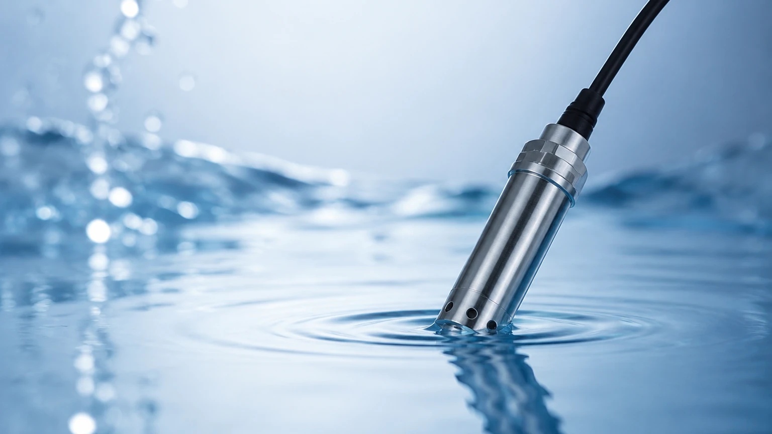
4. Cable Protection: For submersible sensors, ensure the cable is secured with a proper suspension clamp. Avoid sharp bends in the cable, which can pinch the internal vent tube and cause measurement drift.
Limitations and Potential Risks
While liquid pressure sensors are versatile, they have inherent limitations that must be managed:
* Density Sensitivity: Since hydrostatic pressure depends on density, any change in the liquid's concentration or temperature will change the level reading. If the liquid density varies significantly, a continuous density compensation system or a non-contact method like radar might be more appropriate.
* Mechanical Clogging: In liquids with high solids content, the small pressure ports of standard transmitters can clog. Flush diaphragm designs are the standard solution for these "dirty" applications.
* Atmospheric Fluctuations: In very shallow tanks (e.g., less than 1 meter), even small changes in weather-related barometric pressure can cause significant errors if the sensor is not properly vented to the atmosphere.
Frequently Asked Questions (FAQ)
Q: How often should liquid pressure sensors be calibrated?
A: In most industrial applications, an annual calibration check is standard. However, in critical safety applications or harsh environments with high pressure spikes, semi-annual calibration may be required to account for potential sensor drift.
Q: Can a liquid pressure sensor be used for boiling liquids?
A: It is challenging. Boiling creates bubbles (gas) within the liquid, which changes the effective density and creates significant turbulence. In these cases, a remote seal system with a capillary tube may be used to move the electronics away from the heat, but non-contact level measurement is often preferred.
Q: What is the difference between a pressure transducer and a pressure transmitter?
A: While the terms are often used interchangeably, a transducer typically outputs a raw voltage signal (mV), while a transmitter includes signal conditioning electronics to provide a robust industrial output like 4-20mA.
Engineering Summary
Liquid pressure sensors remain a cornerstone of industrial process control due to their reliability and cost-effectiveness. By understanding the relationship between pressure, density, and height, and by matching the sensor material to the process media, engineers can implement robust measurement solutions. For those looking to integrate these sensors into broader automation frameworks, reviewing the latest technical specifications on the Main Page is a recommended next step to ensure all application-specific requirements are met. Proper attention to installation details, such as venting and turbulence protection, will ensure long-term accuracy and minimal maintenance requirements in the field.