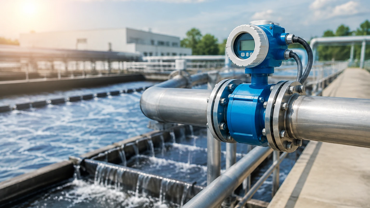
Magmeter Flow Meter
Magmeter Flow Meter
In the landscape of industrial process control, the magmeter flow meter—formally known as an electromagnetic flow meter—stands as a cornerstone technology for measuring the flow of conductive liquids. Unlike mechanical flow meters that rely on moving parts such as turbines or gears, the magmeter operates on electronic principles, offering a non-intrusive solution that minimizes pressure drop and maintenance requirements. This guide provides a technical overview of magmeter technology, its selection criteria, and its integration into broader industrial measurement systems.
Measurement Principles of Electromagnetic Flow Meters
The operation of a magmeter flow meter is based on Faraday’s Law of Electromagnetic Induction. This principle states that a voltage is induced when a conductive medium passes through a magnetic field. In the context of a flow meter, the "conductor" is the process liquid itself.
The Mathematical Foundation
The relationship is defined by the equation:
E = kBDv
* E: The induced voltage (signal generated).
* k: A constant specific to the instrument.
* B: The strength of the magnetic field generated by the meter’s coils.
* D: The distance between the electrodes (internal diameter of the pipe).
* v: The average velocity of the liquid.
As the liquid flows through the pipe, the magnetic coils within the meter body generate a controlled magnetic field. Two electrodes, positioned flush with the pipe wall, detect the voltage generated by the moving liquid. Because the magnetic field strength (B) and the pipe diameter (D) are fixed, the induced voltage (E) is directly proportional to the flow velocity (v). The internal transmitter then converts this voltage into a standardized signal, such as 4-20mA, pulse, or digital protocols like Modbus or HART.
Conductivity Requirements
A critical limitation of this principle is the requirement for electrical conductivity. For a magmeter flow meter to function, the liquid must have a minimum conductivity, typically 5 μS/cm (microsiemens per centimeter) or higher. This makes the technology ideal for water, acids, bases, and slurries, but unsuitable for hydrocarbons, distilled water, or gases.
Key Components and Construction
A magmeter consists of two primary assemblies: the sensor (flow tube) and the transmitter (electronics). Understanding the materials used in these components is essential for ensuring long-term reliability in harsh environments.
Liner Materials
Since the flow tube is often made of stainless steel or carbon steel, it must be lined with an insulating material to prevent the induced voltage from shorting out against the pipe wall. Common liners include:
* PTFE (Polytetrafluoroethylene): Excellent chemical resistance and high-temperature tolerance. Ideal for aggressive acids and bases.
* PFA (Perfluoroalkoxy): Similar to PTFE but with better mechanical strength at high temperatures and superior resistance to vacuum collapse.
* Neoprene/Hard Rubber: Frequently used in water treatment and for abrasive slurries due to its durability and cost-effectiveness.
* Polyurethane: Highly resistant to abrasion, making it the standard choice for mining and wastewater applications involving solids.
Electrode Materials
The electrodes must be compatible with the process fluid to prevent corrosion or scaling. Standard options include:
* 316L Stainless Steel: Suitable for water and mildly corrosive liquids.
* Hastelloy C: Used for more aggressive chemical applications.
* Titanium/Tantalum: Reserved for highly corrosive environments, such as chlorine or concentrated acids.
* Platinum-Iridium: Used in specialized pharmaceutical or highly reactive chemical processes.
Selection Criteria for Industrial Applications
Choosing the right magmeter flow meter requires a detailed analysis of the process conditions. Engineers must look beyond pipe size and consider the fluid dynamics and chemical interactions within the system.
1. Velocity and Turndown Ratio
Magmeters are most accurate when the fluid velocity is between 0.5 m/s and 10 m/s. If the pipe is oversized for the application, the velocity may drop below the meter’s sensitivity threshold, leading to inaccuracies. Conversely, excessively high velocities can cause liner wear and increased pressure loss.
2. Accuracy and Repeatability
Standard industrial magmeters typically offer an accuracy of ±0.5% of the flow rate. High-precision models can achieve ±0.2%. For billing or custody transfer applications, these tighter tolerances are often mandatory.
3. Integration with Level Measurement
In many industrial setups, flow measurement is paired with level measurement to provide a complete picture of mass balance. For instance, in a chemical storage tank, a magmeter tracks the output while a radar or ultrasonic sensor monitors the remaining volume. For professionals managing these integrated systems, visiting the Main Page of instrumentation providers like Welk offers insights into how level measurement instruments can be synchronized with flow data for automated process control.
Selection Summary Table
| Application | Recommended Liner | Recommended Electrode | Typical Accuracy |
| :— | :— | :— | :— |
| Potable Water | EPDM / Hard Rubber | 316L SS | ±0.5% |
| Aggressive Chemicals | PTFE / PFA | Tantalum / Hastelloy | ±0.2% – 0.5% |
| Mining Slurries | Polyurethane | Tungsten Carbide | ±0.5% |
| Food & Beverage | PFA (FDA approved) | 316L SS (Polished) | ±0.25% |
Installation Guidelines and Best Practices
The performance of a magmeter flow meter is heavily dependent on the quality of the installation. Improper placement or grounding is the most common cause of measurement error.
Straight Pipe Runs
To ensure a stable, laminar flow profile, magmeters require a specific amount of straight pipe before and after the sensor. The industry standard is typically:
* Upstream: 5 times the nominal diameter (5D).
* Downstream: 2 times the nominal diameter (2D).
If there are pumps or valves immediately upstream, these requirements may increase to 10D to eliminate turbulence.
Grounding and Potential Equalization
Because the induced voltage is extremely small (often in the millivolt range), it is susceptible to electrical noise. The meter must be properly grounded to the process liquid. If the pipe is unlined metal, grounding to the pipe is usually sufficient. However, if the pipe is plastic or lined, grounding rings or specialized grounding electrodes are required to establish a reference point for the signal.
Orientation and Full Pipe Requirement
Magmeters must always be installed in a location where the pipe remains completely full. If the pipe is partially empty, the meter will over-read or fail to provide a stable measurement.
* Vertical Installation: Flow should move upward to ensure the pipe is full and to prevent air bubbles from trapping at the electrodes.
* Horizontal Installation: The electrodes should be positioned at the 3 o'clock and 9 o'clock positions. Placing them at the top (12 o'clock) risks air interference, while the bottom (6 o'clock) risks sediment buildup.
Common Risks and Limitations
While the magmeter flow meter is highly versatile, it is not a "one-size-fits-all" solution. Engineers must be aware of specific environmental and fluid-related risks.
1. Vacuum Conditions: In certain chemical processes, a vacuum can be created within the pipe. If the liner (such as PTFE) is not mechanically bonded to the flow tube, the vacuum can cause the liner to collapse or peel away, destroying the meter.
2. Fluid Conductivity: As mentioned, non-conductive fluids like oils or pure hydrocarbons cannot be measured. If the conductivity of the fluid changes significantly during the process, the meter may require recalibration or a different measurement technology.
3. Coating and Scaling: If the process fluid is prone to leaving deposits (e.g., calcium buildup or oily films), the electrodes may become insulated from the liquid. Some advanced magmeters feature electrode cleaning circuits or removable electrodes to mitigate this risk.
4. Ambient Interference: High-power equipment, such as large motors or variable frequency drives (VFDs) located near the meter, can introduce electromagnetic interference (EMI). Shielded cabling and proper separation are necessary in these environments.
Comparison with Other Flow Technologies
To understand the value of a magmeter, it is helpful to compare it against other common flow measurement technologies used in industrial automation.
* Magmeter vs. Ultrasonic: Ultrasonic meters (Transit-time) can be clamped onto the outside of the pipe, which is an advantage for retrofitting. However, magmeters are generally more accurate for liquids with entrained solids or bubbles, which can scatter ultrasonic signals.
* Magmeter vs. Vortex: Vortex meters are excellent for steam and gas, but they require a minimum flow velocity to function and create a pressure drop. Magmeters offer a much wider turndown ratio for liquids and zero pressure drop.
* Magmeter vs. Differential Pressure (DP): DP meters (using orifice plates) are traditional and low-cost but have high maintenance needs due to wear and clogging. The magmeter’s lack of moving parts makes it a superior long-term investment for conductive liquids.
Frequently Asked Questions (FAQs)
Can a magmeter measure flow in both directions?
Yes, most modern magmeters are bi-directional. They can be configured to measure flow in both forward and reverse directions, providing separate totals for each. This is particularly useful in water distribution networks and tank loading/unloading applications.
What is the typical lifespan of a magmeter flow meter?
In non-corrosive water applications, a well-installed magmeter can last 20 years or more. In abrasive or highly corrosive chemical applications, the lifespan depends entirely on the selection of the liner and electrode materials. Regular inspection of the liner is recommended in these cases.
Does the viscosity of the liquid affect the measurement?
No. One of the primary advantages of electromagnetic flow measurement is that it is independent of liquid viscosity, density, and temperature, provided the conductivity remains above the minimum threshold and the flow remains laminar or predictably turbulent.
How often should a magmeter be calibrated?
For most industrial applications, an annual verification is sufficient. Many modern transmitters include "self-verification" features that check the integrity of the coils and electrodes without removing the meter from the line. However, for regulated industries like pharmaceutical or food production, annual laboratory calibration may be required.
Can I use a magmeter for deionized (DI) water?
Generally, no. Deionized water has very low conductivity, often below the 5 μS/cm threshold required for the induction principle to work. For DI water, ultrasonic or vortex flow meters are typically recommended.
Conclusion
The magmeter flow meter remains a vital tool for industrial liquid measurement due to its accuracy, lack of moving parts, and minimal maintenance requirements. By carefully selecting liner and electrode materials and adhering to strict installation standards regarding grounding and pipe runs, engineers can ensure reliable data for years of operation. For those looking to integrate flow data with tank level monitoring, exploring the range of radar and ultrasonic solutions on the Main Page can help create a more cohesive and automated process environment.